MAST (Maximum Allowable Stem Torque)
We know ball valves (rotary valves) are used as ESDVs/BDVs in critical services like shutdown, isolation and blow down application.
As an engineer we always ensure reliability and integrity of actuator and its components.
However as far as stem components are concerned we either give little attention to mechanical integrity of stem or sometimes we leave it to valve vendor and assume
“Stem design is sufficient enough to withstand actuator torque”.
Always it is not true, Stems do fail!!!
If stem key of an ESDV is failed OR damaged in open position……. What can happen …?
It will not close when there is a close command and this may lead to disastrous situation …
MAST: Definition & its importance
It is maximum allowable torque a stem of a quarter turn valve can be subjected to without mechanical failure. Engineering unit Nm OR lb-in
During valve operation, torque delivered by actuator (Pneumatic or electric) at any stage, should not exceed MAST value. If it happens stem may be subjected to mechanical failure.
In some projects it has happened that MAST value calculated by valve vendor was higher than actual, even than it resulted in failure of stem.
MAST value: Definition & its importance
This is valve manufactures responsibility to calculate and provide valve MAST during engineering stage and ensure torque delivered by actuator is always less than the valve MAST.
During offer stage valve MAST furnished in performance table shall be considered as basic value. During engineering stage ideally 3-4 weeks after PO, Valve manufacture must submit Valve MAST calculation same shall be reviewed and approved by responsible engineer. Requirement of valve MAST calculation shall be indicated in SDRL
To study the concept of MAST, first we need to know few of the valve internals and the stresses developed during the valve operation.
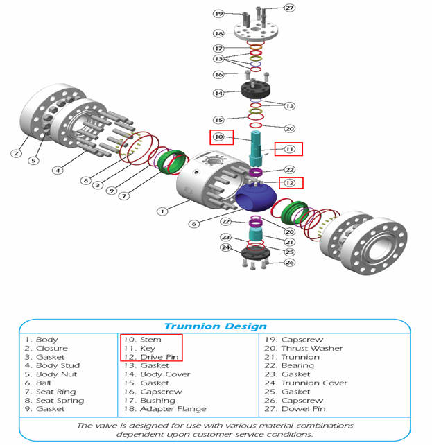
Drive train & its component
Drive Train: Definition as per API 6D “All parts of a valve drive between the operator and obturator (Ball /Disc), including obturator but excluding the operator.
Drive Train components in a ball valve are
1. Solid round stem
2. Stem key: Keys are used to transmit torque from actuator to stem
3. Ball & Stem joint (there are two types of Ball & Stem joint)
a) Ball & stem joint with dowel pins – Type A
b) Ball & stem spliced joint –rectangular section of stem fits into matching groove in the Ball- Type B
Ball valve design – Round (solid) bar Stem with Ball connection using drive / dowel pin (Type A)
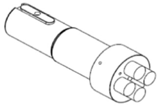
Ball valve design
Round (solid) bar Stem with Ball connection using drive / dowel pin (Type A)
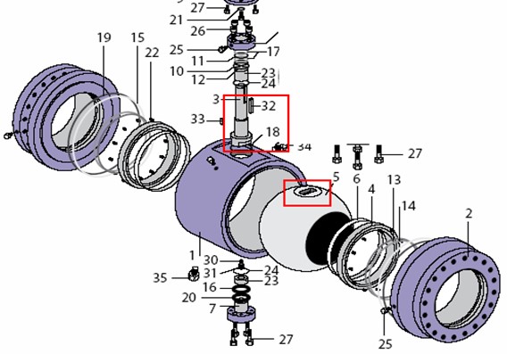
Ball valve design Type B
Ball valve design – Round (solid) bar Stem with rectangular cross section at the end of stem for connection with Ball Spliced joint (Type B)
Actuator Coupling
Actuator Coupling
Stresses in different drive train
Stem components are subject to following types of stress when operating torque is applied by an actuator to achieve desired operation (opening / closing /running)
Stem- torsional shear stress
Stem key – torsional shear stress+ bearing stress
Dowel /drive pin Joint or spliced joint- torsional shear stress+ bearing stress
Stem under Torsional shear stress
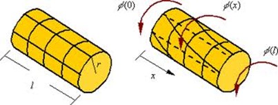
Stem under Torsional shear stress
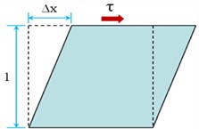
Key under shear stress
Key under Bearing Stress
Forces are generated at the contact surface between the member and the connecting element.
Consequently stresses are produced on the common contact surface (bearing surface).
Bearing Stress = Resultant force at the contact surface
Projected Area of the contact surface normal to the resultant force
Valve torque calculation:
Assumption for the calculation:
a) Ball valve with solid circular stem & connection to ball by dowel pins – (Type A).
b) Ball valve with solid circular stem & rectangular cross-section at the end of stem for connection to ball-(Type B)
(Valve / Actuator mounting bracket design ISO 5211 and stress calculation Not covered in this presentation).
c) This guide is applicable to trunnion mounted ball valves only.
d) This guide is limited to maximum allowed torque calculation for valve stem & its components only.
e)The torsional and shear stress limits used for calculation of maximum allowable torques are based on ASME code Section VIII, Div2, Part AD-132 and same is in line with section 7.20.2 (Allowable stresses) of API 6D.
f) Yield strength (YS)- “ THE ABILITY OF METAL TO TOLERATE THE STRESS WITHOUT PERMANENT DEFORMATION ” The Yield strength (YS) used in calculation must be as stated in ASTM for the corresponding material and grade. Engineering unit – N/m2 or Mpa.
Basis for the calculation:
Based on Material of construction (MOC) of stem , Stem key & dowel pins the maximum allowed stress on each individual components are calculated ( Reference ASME code Section VIII, Div2, Part AD-132 & ASME code Section II, Part D,Ed2010)
The values of maximum allowed stress are then used to calculate maximum allowable torque based on shape & size of each components (formulas used for calculation of maximum allowable torque is based on normal formulas of physics)
Sm (Design stress intensity value) = 2/3*YS (ASME code Section II, Part D,Ed2010)
Maximum allowable torsional shear stress on stem = 0.8 *(Sm)=0.53*YS (YS= Yield strength of Stem MOC, N/mm^2- Available in ASTM for selected grade)
Maximum allowable Avg. primary shear stress on stem key & Dowels = 0.6 *Sm=0.4*YS (YS= Yield strength of Stem key MOC, N/mm^2 Available in ASTM for selected grade)
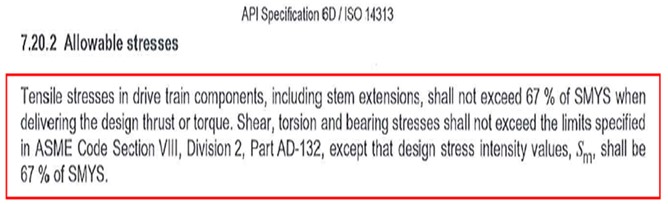
ASME code Section VIII, Div2, Part AD-132
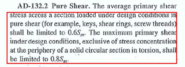
ASME code Section VIII, Div2, Part AD-132
API6D /ISO 14313 (Design specification for Ball valves) Reference
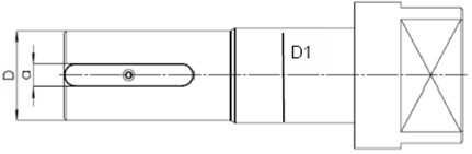
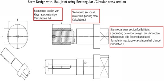
Calculation for Stem design with Ball joint using Rectangular / Circular cross section
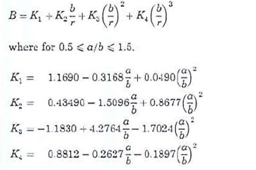
Calculation 1A (Maximum allowable stem torque with 1 key )
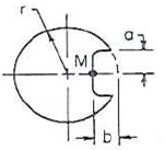
Basis Roark’s formula 28 (Table 10.1)
Calculation 1B (Maximum allowable stem torque with 2 key)
Mc 1 (Max allowable torque with 2 key) = (0.8 *(0.67*Ys)* r ^3)/ B * 1000 Nm
Where r= D/2 (Reduced stem dia at actuator side), in mm
Basis Roark’s formula 29
This portion of calculation can be alternatively done based on Polar movement of inertia or any other method, same needs to be reviewed case by case basis.
Calculation 2 (Maximum allowable stem torque in round section)
Mc 2 (Max allowable torque in round section) = (0.8 *(0.67*Ys)*3.14* d ^3)/ 16000 Nm
Where d is stem dia at round section
Calculation 3A (Maximum allowable stem torque in rectangular section)
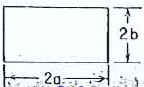
Basis Roark’s formula 4
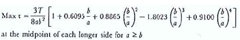
Mc 3A = (0.8 *(0.67*Ys)*(B *h^2)/ (3+1.8*h/B))/1000 Nm
Where Mc = Max allowable torque on rectangular section area, Nm
B= (2a) Rectangular section length, mm
h= (2b) Rectangular section width, mm
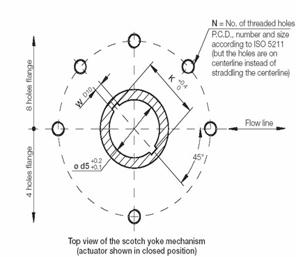
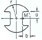
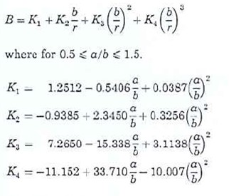
Calculation 3B (Maximum allowable stem torque in Circular section with opposite flattened side)
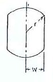
Basis Roark’s formula 9 (Table 20)
h=r-w
Mc 3B= (0.8 *(0.67*Ys)* r ^3)/ B * 1000 Nm, where r, h & w in mm
Calculation 4 (Maximum allowable torque on Stem keys)
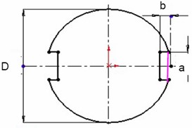
Mc 4 = [(0.6*Sm*D*L*a) / 2000]*n
Mc 4 = [(0.6*0.67*Ys*D*L*a) / 2000]*n
Where, a = width key
L = length key
n = number key
r = stem radius
b = groove key
Where a, L, r, b in mm and Mc in Nm
Valve MAST = Min (MC1, MC2, MC3, MC4)
Valve MAST shall be the lowest value maximum allowable torque in drive train component i.e MC1, MC2, MC3 & MC4
- Calculation for Stem design with Ball joint using Dowel pins
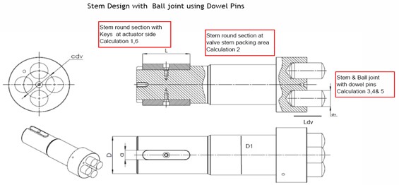
Calculation 5: (Maximum allowable torque at dowels)
MC 5 = [A* (0.6*0.67*Ys)*(cdv/2000)] Nm
A= (Ns*3.14*d^2)/4
Where A= Dowel cross section area, mm^2
cdv=center to center distance between dowels , mm
d= dowel diameter, mm
YS= Yield strength of dowel MOC, N/mm^2
Calculation 6: (Specific loads at dowels)
SL= [Mt / (cdv/2)/1000]
Calculation 7: (Specific pressure on dowels)
SPd = [(SL/(dv*Ldv/2))/Ns]
SPd< YS of dowels
Where Mt = Max actuator output torque, Nm
SL= Specific loads on dowel, N
σd max = maximum allowed stress on dowel , N/mm^2
SPd= Specific pressure on dowel, N/mm^2, Bearing stress on dowel
Ns= Number of dowels
dv= dowel diameter, mm
Ldv= dowel length, mm
YS= Yield strength of dowel MOC, N/mm^2
Who will provide MAST value?
This is valve manufactures responsibility to calculate and provide valve MAST during engineering stage and ensure torque delivered by actuator is always less than the valve MAST.
What stage we should get MAST value?
During offer stage valve MAST furnished in performance table shall be considered as basic value. During engineering stage ideally 3-4 weeks after PO, Valve manufacture must submit Valve MAST calculation same shall be reviewed and approved by responsible engineer. Requirement of valve MAST calculation shall be indicated in SDRL
Please sand details