Pipe rack piping study:
My this post explains the steps required to be performed for carrying out pipe rack piping study.
General arrangement of the piperack is finalized during the development of the overall plot plan. The piperack may be an integral part of a process unit located in the middle of the unit or it may be an arterial part connecting several services of other process units.
The following data and drawings are required to be studied before starting the detailed design of pipe rack piping study:
- Unit Plot Plan / Overall Plot Plan
- Piping and Instrumentation diagrams
- Plant layout specification
- Client specification
- Material of construction
- Fireproofing requirements
Normally, the piperack piping study, with its structural and platform requirements is the first priority item for detail engineering of a process unit.
The points which are finalized during the piperack piping study are:
- Exact width of the piperack
- Numbers of levels and elevations
- Access and maintenance platforms requirements
There are number of pipelines which are routed through the pipe rack. Before starting the pipe rack piping study it is essential to classify these pipelines. Pipelines in the pipe rack are classified as process lines, relief-line headers and utility headers.
Process lines:
(a) Which interconnect nozzles on process equipment more than 20ft. apart (closer process equipment can be directly interconnected with pipelines)
(b) Product lines which run from vessels, exchangers, or more often from pumps to the unit limits to storage or header arrangement outside the plant.
(c) Crude or other charge lines which enter the unit and usually run in the yard before connecting to exchangers, furnaces or other process equipment e.g. holding drums or booster pumps.
Relief-line headers:
Individual relief lines, blow down lines and flare lines should be self draining from all relief valve outlets to knock-out drum, flare stack or to a point at the plant limit. A pocketed relief line system is more expensive, because usually an extra condensate pot is required with instruments, valves and pumps. To eliminate pockets some relief line headers must be placed at higher elevation above the main yard usually on a tee support on the extended pipe rack column. However, on some non-condensing gas systems self drainage is not so essential. Relief lines can be individual, some with large diameters and occasionally high temperatures.
Utility lines:
Utility lines in the pipe rack can be put in two groups:
(a) Utility headers serving equipment in the whole plant. Such lines are: low and high pressure steam lines, steam condensate, plant air and instrument air lines. If required, cooling water supply and return and service water can also be arranged on the pipe rack.
(b) Utility lines serving individually one or two equipment items or a group of similar equipment (furnaces, compressors) in the plant. Such lines are: boiler feedwater, smoothering steam, compressor starting air, various fuel oil lines, lubricating oil, cooling oil, fuel gas, inert gas and chemical treating lines.
Steam header should drain to the steam separator for more effective condensate collection.
Branch connections to steam headers usually connect to the top to avoid condensate drainage to equipment.
Instrument lines and Electrical cables:
Instrument lines and Electrical cables are often supported in the yard and extra space should be provided for these facilities. The best instrument line arrangement eliminates almost all elevation changes between the plant and the control room. This can be easily achieved when instrument lines are supported outside the pipe rack column on a suitable elevation.
STEPS TO PIPE RACK PIPING:
- The first step in the development of any pipe rack is the generation of a line-routing diagram. A line routing diagram is a schematic representation of all process piping systems drawn on a copy of pipe rack general arrangement drawing / or on the unit plot plan where the pipe rack runs in the middle of the process unit.
Based on the information available on the first issue of P&I Diagram / Process flow diagram i.e. line size, line number, pipe material, operating temperature etc. the line routing diagram is to be completed.
- Once the routing diagram is complete, the development of rack width, structural column spacing, road crossing span, numbers of levels and their elevations should be started.
Pipe rack column spacing shall be decided based on the economics of the pipe span as well as the truss arrangement to accommodate double the span for road crossing or avoiding underground obstructions.
Pipe rack arrangement should be developed to suit the specific plant requirements.
- The pipe rack width can now be worked out with a typical cross-section of the rack with the levels.
Normally, pipe racks carry process lines on the lower level or levels and the utility lines on the top level. Instrument and electrical trays are integrated on the utility level if space permits or on a separate level above all pipe levels.
Any pipe rack design should provide provision for future growth to the extent of 25 to 30% on the rack clear width.
When flanges or flanged valves are required on two adjacent lines, the flanges are to be staggered.
Thermal expansion or contraction must be accommodated by keeping sufficient clearance at the location where the movements will occur.
The clearance of the first line from the structural pipe rack column is to be established based on the sizes furnished by the civil / structural engineers.
- After analyzing all the requirements and arrangements, the dimensions are to be rounded off to the next whole number. Based on the economics, the width and the number levels e.g. two tier of 30 ft. wide or three tiers of 20 ft. wide rack will be decided.
The gap between the tiers shall be decided on the basis of the largest diameter pipeline and its branching. The difference between the bottom line of pipe in the rack and the bottom of a branch as it leaves the rack shall be decided carefully, to avoid any interference due to support, insulation, size of branch etc. All branch lines from the main lines on pipe rack shall be taken aesthetically on a common top of steel (TOS).
With the above considerations, the conceptual arrangement of pipe rack is to be finalized.
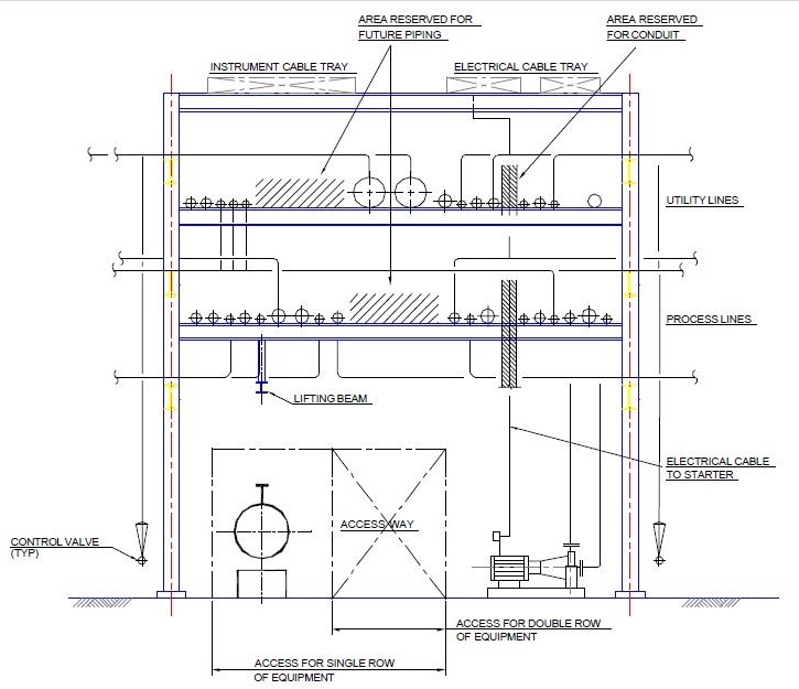
Figure: Typical cross-section for composite piperack