CHECKLIST FOR HELIDECK DESIGN IN OFFHORE PLATFORM |
|||
| Note: | |||
| 1. This Checklist is for Fixed Offshore installations only. | |||
| 2. For specific requirements of Floating / mobile units (e.g. FPSO) Chapter 9 of CAP 437, CAA 2008/03 publication, Chapter 3 & 4 of ICAO Annexure 14 shall be referred for considerations on helideck locations, Dynamic Landing etc. | |||
| 3. For Helicopter Winching Areas on vessels and Wind Turbine Platforms, refer Chapter 10 of CAP 437. | |||
SL NO. |
DESCRIPTION |
Y/ N/A |
REMARKS |
| 1 | Industry Standards referred: (Mention Version/Edition used as per client requirement in Remarks) | ||
| 1.1 | i) CAP 437 Offshore Helicopter Landing Areas – Guidance on Standards | ||
| 1.2 | ii) ICAO Annexure 14 Volume-II Heliports | ||
| 1.3 | iii) CAA Paper 2008/03 : Helideck Design Considerations – Environmental Effects | ||
| 1.4 | iv) HSE – Offshore Helideck Design Guidelines | ||
| 1.5 | v) API RP 2L : Recommended Practice for Planning, designing and Constructing Heliports for Fixed Offshore Platforms. | ||
| 1.6 | vi) Oil & Gas UK – UKOOA-Guidelines for the Management of Offshore Helideck Operations | ||
| 1.7 | vii) NORSOK Standard – C004 – Helicopter Deck on Offshore installations | ||
| 1.8 | viii) Local Aviation Authority Regulations and requirements (if applicable) | ||
| 1.9 | ix) Client Guidelines / Standards / Specifications / Requirements in Scope of Work | ||
| 2 | Helideck Location, Orientation and Elevation: | ||
| 2.1 | Constraints due to adjacent existing and new facilities are reviewed in the Overall Field layout | ||
| 2.2 | Safety hazards from permanent platforms located at immediate proximity (e.g. Bridge linked platforms) are assessed | ||
| 2.3 | Effects of temporary installations and operations like Drilling/ Work over Rigs, jack Up rigs approach and operational areas are assessed | ||
| 2.4 | Preferably located upwind, optional location cross wind. | ||
| 2.5 | Located in Safe area away from Hydrocarbon facilities | ||
| 2.6 | Clear from turbulence & thermal effects cause by exhaust emissions from Gas Turbines | ||
| 2.7 | Away from unburnt hydrocarbon gas emissions from cold flaring / vent boom and emergency blow down systems | ||
| 2.8 | Away from thermal effects of flares, smoke & turbulence from Diesel generators | ||
| 2.9 | Away from Emergency Gas release systems | ||
| 2.10 | Preferably located at corner or edge of platform with about 50% overhang | ||
| 2.11 | Clear from any vertical structures, Euqipments, cranes on the platform in 210° Obstacle free sector. (Vertical projections are planned only in 150° limited Obstacle Sector (LOS) and respects the LOS segment limits) | ||
| 2.12 | Tall / Large Structures like Derricks are not located upwind of Helideck to prevent any air turbulence. | ||
| 2.13 | 180° Sector 5:1 Falling Gradient below the landing area (measured from outer edge of safety net) till water level does not contain any deck projections / mobile installations beyond available limit (falling obstacle limitation surface) | ||
| 2.14 | Orient 210° Obstacle free sector such that Helicopter Approach is opposite (preferable) or cross wind to prevailing wind direction. Wind Rose diagram referred for seasonal wind patterns for finalizing the most suited orientation. | ||
| 2.15 | Solar Panel Deck is located below Helideck and not in 180°5:1 Falling Gradient sector. | ||
| 2.16 | Ensure sufficient Air Gap below helideck (3m to 5m) to avoid vertical & turbulent air flow above helideck. | ||
| 2.17 | Maximum Helideck height is (preferably) limited within 60m above sea water level | ||
| 2.18 | Minimum Height of Helideck from Sea Water level is meeting operational limitations specified by Aviation Authority. (As a normal practice, maintain a minimum height of 15m above water level) | ||
| 2.19 | Provisions for Fire Water lines, Guttering system are considered | ||
| 3 | Helideck Design: | ||
| 3.1 | The take-off and landing area is designed for the heaviest and largest helicopter anticipated to use the facility | ||
| 3.2 | Type of Helicopter is considered as per client inputs / as per scope of work | ||
| 3.3 | Deck shape is considered as per client requirements | ||
| 3.4 | D’ Value considered as per as per standards or as per client inputs | ||
| 3.5 | The ‘D’ Value considered is in conformity to the value mentioned in standards (CAP437/API RP-2L) for the type of Helicopter mentioned in Scope Of Work. | ||
| 3.6 | The ‘t’ Value considered is in conformity to the value mentioned in standards (CAP437/API RP-2L) for the type of Helicopter mentioned in Scope Of Work. | ||
| 3.7 | Helideck perimeter Safety Net of 1.5m wide in the horizontal plane with upward and outward slope of 10°is provided. | ||
| 3.8 | Any re-fuelling facilities to be considered? (if necessary) | ||
| 3.9 | Helicopter parking area requirement considered? (if necessary) | ||
| 4 | Access and Evacuation: | ||
| 4.1 | Ensure that there are a minimum of two access/egress routes on the helideck to the Stairways, which are arranged such that personnel will be able to escape upwind of the landing area. | ||
| 4.2 | Based on HSE recommendations for evacuation, escape and rescue analysis, third escape route leading to stairway / hatch for emergency ladder is considered if required. | ||
| 4.3 | Escape routes are arranged such that embarking and disembarking passengers are not required to pass around the helicopter tail rotor, or around the nose of helicopters having a low profile main rotor. | ||
| 4.4 | Escape routes leading to stairways on the 5:1 Falling Gradient sector shall be avoided | ||
| 4.5 | The stairways provided are going down, straight out from and perpendicular to the edges of the helideck to the landing platforms with no handrails protruding above the helideck. | ||
| 4.6 | The minimum width of the stair way/landing is maintained as required in project specific Emergency Escape and Rescue document. | ||
| 4.7 | The Height of the objects required to be located on the edge of the Helideck / intermediate platform (lighting, Fire monitors, Wind Sock etc.) is not higher than 25 cm above the Helideck landing area. | ||
| 4.8 | The helideck is readily accessible from the living area/escape route. | ||
| 5 | Helideck drawing: | ||
| 5.1 | Helideck and other markings are drawn as per dimensional requirements based on ‘D’ value | ||
| 5.2 | The perimeter marking of the landing area is clearly shown with line 30 cm wide. | ||
| 5.3 | The actual D-value of the helideck marked on the 210°angle sector below of the chevron. | ||
| 5.4 | The Perimeter ‘D’ Marking is shown | ||
| 5.5 | The origin of the 210° OFS for approach and take-off is drawn by a black chevron forming the angle of 210°. | ||
| 5.6 | Maximum allowable mass marking is shown in a position at the preferred final approach direction. | ||
| 5.7 | Touchdown/Positioning Marking (TD/PM) is shown and centre of TD/PM is concentric with the centre of the D-circle. | ||
| 5.8 | H’ marking is shown within TD/PM with the cross bar of the ‘H’ lying along the bisector of the OFS. | ||
| 5.9 | Helideck Name Block (identification marking) is shown between the origin of the OFS and the TD/PM Circle. | ||
| 5.10 | Prohibited landing heading sectors are shown if applicable. | ||
| 5.11 | 210° OFS for Helicopter approach and take-off is shown on the layout | ||
| 5.12 | 150°Limited Obstruction sector is shown on the layout. | ||
| 5.13 | 180° 5:1 falling gradient is marked on helideck layout falling gradient origin is at the centre of the D-circle. | ||
| 5.14 | 5:1 Falling Gradient line is shown in the Platform Elevation Views. | ||
| 5.15 | The helicopter Approach direction is shown. | ||
| 5.16 | Safety Net Shown | ||
| 5.17 | Primary and secondary Escape routes shown | ||
| 5.18 | Stairways to Intermediate platform / below deck shown | ||
| 5.19 | Facilities located on the intermediate platform (e.g. Fire Monitors, Rescue Kits, Navigation Aids, Wind Sock) are shown | ||
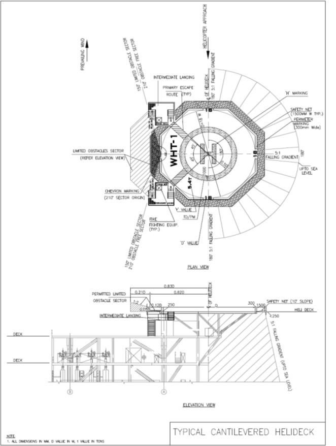
Cantilevered helideck