1.0 Introduction to Cooling Tower:
Cooling Tower is the most common equipment/ facility in any Refinery, Petrochemical and Petroleum plants. Cooling towers are heat exchangers that are used to dissipate large heat loads to the atmosphere generated in the Process Plants.
This design guide provides the guidelines for the designing of the equipment layout and piping arrangement for Cooling Towers.
2.0 Types of Cooling Tower:
There are two types of Cooling Tower:
a) Mechanical Draft
(i) Mechanical Forced Draft
(ii) Mechanical Induced Draft (Refer figure 1, 2, 3 &4)
b) Natural Draft (Refer figure 5 & 6)
The most commonly used in the chemical plants is the Mechanical Induced Draft Cooling Tower which is covered in this document.
3.0 Definitions used for Cooling Tower:
The general terms used for Cooling towers are defined below:
a) Casing
Cooling Tower casing acts to contain water within tower. It is enclosure housing the fill (packing) and drift eliminators.
b) Louvers
These are provided on the sides of the tower to equalize the air flow into the fill and to prevent the water drops from falling out.
c) Fill (Packing)
This is the main component of Cooling Tower responsible for heat transfer and is of two types i.e. splash type and film type.
d) Fill & Tower supporting structure
The fill, casing and fan deck are all supported from the basin.
e) Fan Deck
This is the deck (floor) at the top (above the fill) to provide the access to the fan and water distributing system.
f) Fan
Fans create the required air flow through the tower and are driven by electric motors through gear drives for all towers.
g) Fan cylinders and Recovery stack
Recovery stack is provided above fan cylinder to recover kinetic energy of air thereby reducing the power consumption. Suitable air tight access door shall be provided in the cylinder for approach to the fans and for maintenance of gear box and fans etc. Suitable removable rail with tripod and handrail shall be provided for large cooling towers. It is not essential for the small cooling towers.
h) Drift Eliminators
These are provided at the air outlet from fill, to trap the water particles carried by the air stream and thereby reduce the drift loss.
i) Water Distribution System
In case of cross flow tower the hot tower is fed to hot water basins or troughs located on the top of tower by means of hot water inlet pipes. From this basin, water flows over the fill by gravity through orifices located in hot water basin.
Counter-flow system normally necessitates the use of pressure type system of closed pipe and spray nozzles.
j) Cold Water Basin
This holds the re-cooled water falling through the fill and provides an outlet for the cooled water.
Basin depth may be decided based on following considerations:
a) Flooded suction and NPSH required for cooling water pumps if horizontal pumps are used and submergence and pump dimensions if vertical pump are used.
b) Cooling tower should be able to supply cooling water within acceptable temperature limits under variable cooling loads during normal operation.
c) Cooling tower should be able to supply cooling water within acceptable temperature limits during start-up, shut-down and emergency conditions, if so specified.
d) Basin should be able to hold back-flow during pump shut-down and cooling water shall not overflow into drains. This is particularly important if treated water is used as cooling water make-up or water is scarce and wastage is to be minimized.
e) Basin should have enough reserve capacity during interruption of make-up water supply.
f) If basin is to be used as a reservoir for fire water supply, take inputs from Basic Study for Fire Protection System.
g) For underground basins, soil conditions and ground water table etc. may be checked with civil department while deciding the depth of the basin.
h) In case of large cooling towers with more than 5 cells, the cold water basin may be partitioned into two components along the length of tower and cleaning of one compartment of cold water basin may be carried out by shutting down half part of individual cells of entire cooling tower.
4.0 Design Features of Cooling Towers:
Types of Cooling Towers
It is advisable to provide separate cooling towers for process and utility plants, if there is a possibility of contamination of cooling water in the process plant.
There are two types of Mechanical Induced Draft cooling towers:
Cross-flow tower
Air flow is horizontal across the downward fall of water. (Refer figure 1 & 2)
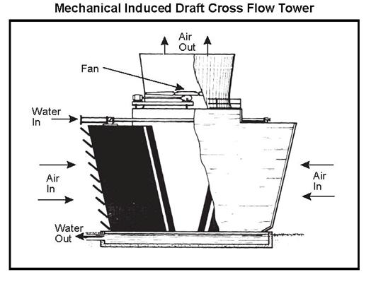
Fig 1- Mechanical Induced Draft Cross-flow Tower
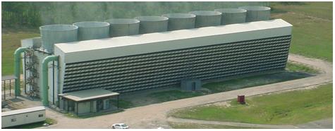
Fig 2- Mechanical Induced Draft Cross-flow Tower
Counter-flow tower
Air and the water flow in opposite in vertical direction. (Refer figure 3 & 4)
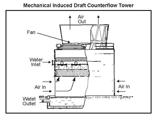
Fig 3 Mechanical Induced Draft Counter-flow Tower
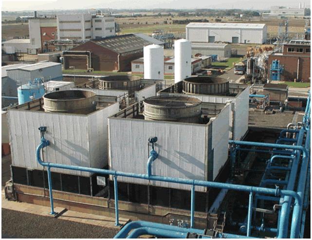
Fig 4 Mechanical Induced Draft Counter-flow Tower
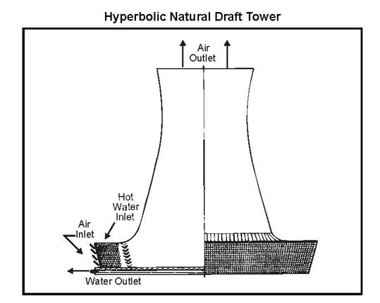
Fig 5 Hyperbolic Natural Draft Tower
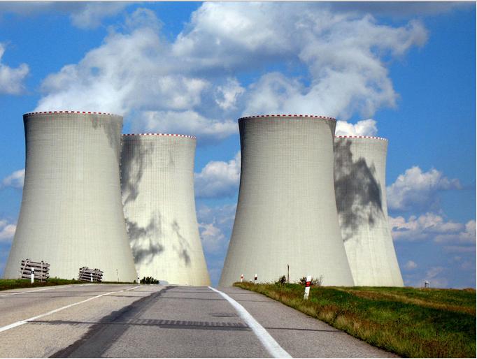
Fig 6 Hyperbolic Natural Draft Tower
Choice of type of Induced Draft Cooling tower
The choice of the tower is left open to the client since none of the types has major advantage. The towers may be single air entry or double air entry type. Single air entry is to be selected when the nearby structure located within distance of one tower height from the cooling tower obstruct the free flow of air. Then the unobstructed side should be considered as the air entry for single air entry type. Otherwise it is preferable to adopt double air entry type.
Number of Cells
Large and medium size towers are of multi-cell, each cell having its own fan, water distribution system, fill, drift eliminators and louvers. This facilitates flexibility of operation by distribution of water load and control of cooling water temperature by operation of required number of cells. The maximum fan tip speed shall be limited to 65 meters per second. On this basis the maximum capacity of each cell shall be about 3000 m3/hr. Depending on the total capacity of tower, number of cells may be selected e.g. 30000 m3/hr capacity tower may have 10 cells.
Materials of Construction
The basic material of construction shall be either of listed below materials,
Timber, Plastics GRP and FRP, Asbestos Cement Board ACB. The material ACB shall be checked with reference to the project location and its design basis.
5.0 Consideration for Design of Basin and Sump
The function of the sump is to supply an evenly distributed flow of water to the suction bell mouth. An uneven distribution of flow, characterized by strong local currents, favour formation of vortices and certain low value of submergence will introduce the air into the pump with reduction in capacity accompanied with noise.
The ideal approach is to have a straight channel coming directly to the pump. Turns and obstructions are detrimental since they may cause eddy currents and tend to initiate deep-cored vortices.
The design of the sump details are mentioned in the drawing Cooling water basin & sump details (Figure 4) which mentions important features of sump design.
The width of sump is illustrated in the drawing in which dimension ‘B’ is suggested as 1.5D or shall be minimum distance for bell mouth. With this, it shall be ensured that distance of 1.5D is not compromised.
Regarding height of the sump, the variable of normal level for water has to be 4D ensuring the total hold up of 6 minutes circulation is taken care. To simplify further the distance between the normal level of the water and the top of the pump casing should have water level equal to 6 minutes of pump circulation. As far as the other variables are concerned, 100mm is being taken for high level and overflow level based on the good engineering practice. Also, free board volume of 200mm is to be taken into account while determining height of the sump.
The length of the sump is generally based on layout requirements, sufficing the pump clearance and its maintenance requirement.
6.0 Layout Aspects of Cooling Tower:
a) Cooling Tower shall be always on the downward wind of Process plant, Admin building. The reason is that wind should not carry water droplets from the cooling tower towards Process plant thus leading to corrosion. In case of Administration building, the water droplets from cooling tower may drift along with the wind and provide showers on the man movement area or the offices.
b) Cooling Tower shall be located so that the clear distance between the tower and any surrounding structure is at least equal to the height of the tower. The vendor recommendation shall also be sought when space limitations is a concern.
c) Orientation of towers:
i) Towers with air inlets on only one side shall be oriented such that the air inlets face the prevailing wind.
ii) Towers with air inlets on opposite sides shall be oriented such that the air inlet sides are either parallel to or at an angle to prevailing wind direction.
d) The top of cooling tower requires permanent approach for inspection and maintenance of the fan decks. Staircase is generally provided as main source of access and the ladder is provided on diagonally opposite side for egress. The number of staircases and ladders may be frozen based on the norms of the local govt. rules / project requirements as applicable.
e) The suction line of the pump shall be provided with the bellows so as to absorb the misalignment that might arise due to construction errors between pump foundation and sump nozzle.
f) The water distribution lines might be buried to minimize problem of thrust loading, thermal expansion and freezing; or elevated to minimize cost of installation and repair. In either case, the risers to the tower inlet must be externally supported, independent of the tower structure and piping.
g) The blowdown line in the return piping shall be provided with the isolation valve at the end of the return header. The purpose is to facilitate the complete flushing before the plant start up. With this provision there is no need to run the water through the cooling towers and therein the prevention of the cooling tower can be taken.
h) Chemical dosing shall be provided in the cooling water system so that the PH value as well as the chlorine content can be maintained in the circulating cooling water system.
i) Side stream filtration line is required to have the continuous filtration of the cooling water line. The blowdown line provided helps to flush the line before the start up of the plant but side stream filtration line is important to have day to day cleaning of the cooling water. The configuration for this line is as follows inlet to the side steam filter has its tapping from cooling water pump outlet line and the outlet of the filter in return is run back to the sump of the cooling tower.
j) The make-up water line is fed to the cooling tower sump so as to provide the minimum water level in the sump.
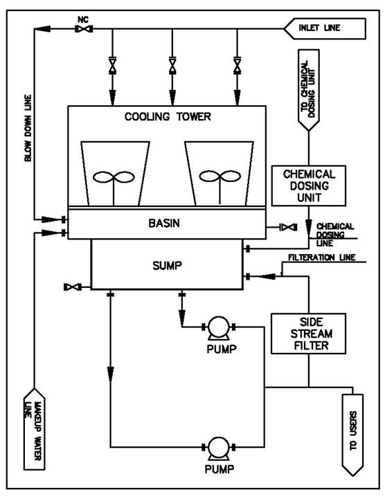
Fig7 Typical-nomenclatures-Cooling-Tower-Piping
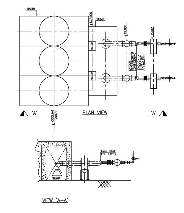
Fig 8 Typical suction piping for a cooling tower
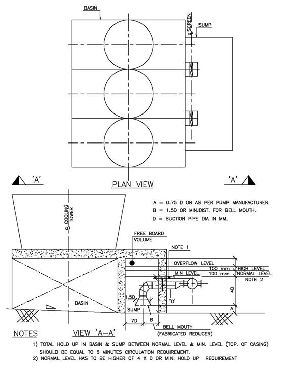
Figure 9: Calculation of a sump height