My previous jetty part 1 post explained method of loading and selection of jetty. This post will cover
- Jetty Head Facility Development
- Checklist for development of Jetty Head layout
Once jetty selection and method of unloading is established one has to review the facility to be developed at jetty head development of jetty head facility can be reviewed broadly based on following points.
A) Area allocation on Jetty Head: Generally jetty authorities identify the area where facility development can be done. Needless to say this is a very narrow strip. But it is always desirable to have this area identified before one starts system developments. In major cases it happens that the in-puts available from client (As-built drawing of existing facility) do not match with existing operating facility, It is usually advisable to do chalk marking of the new facility at the site to ensure smooth construction of system. . Also ensure that the operation of existing facility and Working of fire-fighting system is properly studied as one has to develop a system which does not interfere with existing operations and fire-fighting drills.
B) System to be developed: Development of facility at jetty head is based on following criteria.
B.I Method of Unloading
B.II Number of fluids to be unloaded and their class.
B.III Method of transferring the fluid from Jetty head to the user end.
B.IV Space availability
As above four cases are inter-connected let us take combination of above Cases so that the system understanding becomes simpler.
B.1 Case –1
(UNLOADING IS THROUGH MLA / THREE FLUIDS ARE TO BEUNLOADED {HSD/SKO/MS} / SINGLE PIPELINE IS USEDTO TRANSFER THE FLUID/ SPACE @JETTY HEAD IS ADEQUATE)
As per above combination one has to install pig-launcher at jetty head and pig-receiver at the user end .Pigging philosophy in such case has to be developed before Scheme is finalized.
Pigging philosophy should clearly indicate the method of pigging, number of pigs used when change over of fluid takes place, method of cleaning, cleaning medium used
(AIR/NITROGEN) when change over operation takes place, method of draining the header and automation required to control the system.
B.2 Case –2
(UNLOADING IS THROUGH TAPP-OFF FROM EXISTING MANIFOLDS / THREE FLUIDS ARE TO BEUNLOADED {HSD/SKO/MS / SINGLE PIPELINE IS USED TO TRANSFER THE FLUID/ SPACE @JETTY HEAD IS ADEQUATE)
As per above combination the system of unloading remains same as defined in B.1.
B.3 Case –3
(UNLOADING IS THROUGH TAPP-OFF FROM EXISTING MANIFOLDS OR THROUGH MLA / THREE FLUIDS ARE TO BEUNLOADED {HSD/SKO/MS} / SINGLE PIPELINE IS USED TO TRANSFER THE FLUID/ SPACE AT EXISTING JETTY HEAD IS INADEQUATE)
If the space available is in-adequate then one has to carry the fluid through single pipeline if it is MLA unloading and two pipes if through manifold (usually class A and class B have separate manifolds) outside the jetty area and install pig launcher outside the jetty facility along with slop tank. In such case one will have to install a pump on the slop tank to pump back the drain into the pipeline. Such a installation requires CCOE approval. From operation point this is not a good option, but if space becomes a constraint than this is the only solution.
Checklist for development of Jetty Head layout
Below is the checklist needed to be followed during development of jetty head layout which involves pig launcher apart from specific requirement of project.
1) RL elevations of jetty head and support trestle to correctly identified and co-related with piping elevation (EL0.000) (chart datum).
2) Surface of jetty head to be correctly identified. Some jetty heads have steel base with a bituminous surface. In such case the skid on which the pig launcher is mounted needs to be welded. Preferably try to locate skid of launcher in-line with pile axis.
3) Installation details of MLA base plate to be correctly examined. (Preferably to be done by civil engg.). Spotting line to be correctly identified.
4) One has to ensure that the counter weights of MLA do not clash with any of existing facility in operating condition.
5) Draining of MLA is to be reviewed. (Either in slop tank or Back into the pipeline. Utility services are required if it has to be drained back in the system).
6) Pig-launchers @ jetty head are generally mounted on skid. Installation of the skid to jetty to be reviewed. (Preferably to be done by civil engg ).
7) Pig handling ergonomics to be reviewed. Usually a Jib crane is used along with pig trolley. Adequate space needs to be left behind the launcher for such operation.
8) Piping around pig-launcher needs to be as compact as possible, to avoid trip hazards during neighboring operation. In elevation view one has to ensure that piping does not foul with counter weight of MLA and also does not obstruct any Water monitor path.
9) In case if Pig-launcher and Support trestle are in perpendicular direction i.e. if pipeline takes a turn (1st change of direction after in-line items) before it goes on support trestle, ensure that some straight spool (1.5to2.0 times pig length)is available for the pig to stand before it changes direction.
10) Source of utility services (Air/Nitrogen) should be clearly identified in the scheme. Usually Air/nitrogen is not available at jetty .So a mobile Air compressor and Nitrogen bank with Vapouriser are needed. These facilities are not allowed to be placed @jetty head on permanent basis. In such case one has to provide a manifold @ other end of support trestle and run lines from source to end user.
11) Once the scheme is finalized ensure that inputs used (details Pig-launcher /jib crane/in-line valves/motorized valves/installation of Pig launcher skid with jetty head/Pipe supports if any) are as accurate (dimensional data) as possible. In-case of any tentative data, mention a note identifying a probable change in dimension that can occur. Note that it takes a substantial time to get clearance on such drawings from Port authorities ,Re-cycle of drawing due to any mistake from consultants side can consume lot of time loss to client
12) It is advisable to have a site visit before the scheme is made as it helps to surface out discrepancies if any between the As-built drawing and site conditions.
13) If the space allocated is very narrow than it is advisable to do chalk marking of proposed facility to avoid any construction problems.
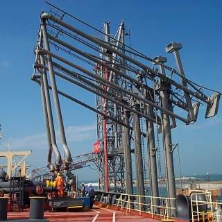
Figure 2: Offshore Mobile loading arm
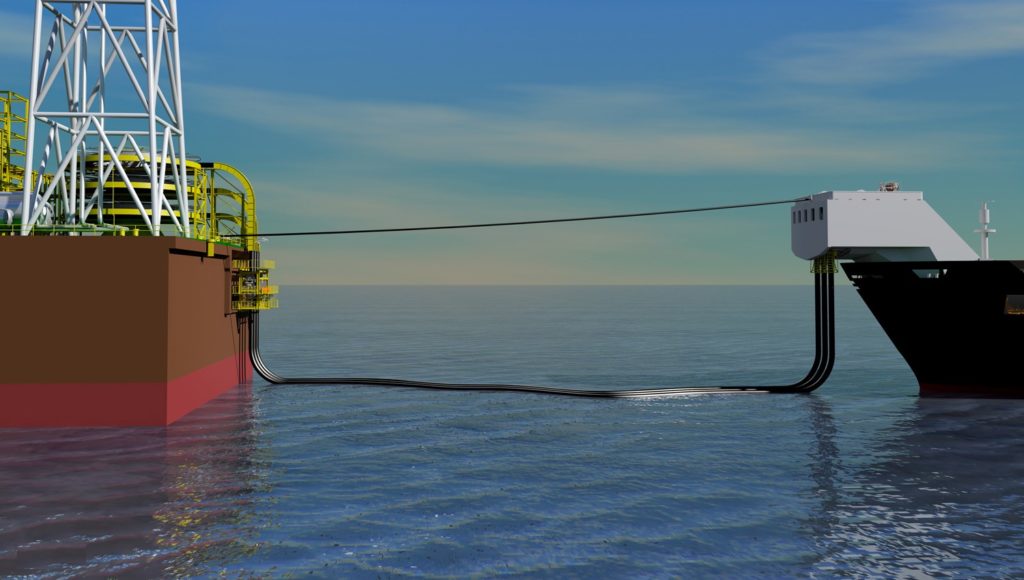
Figure 3: Offshore oil unloading by Hoses