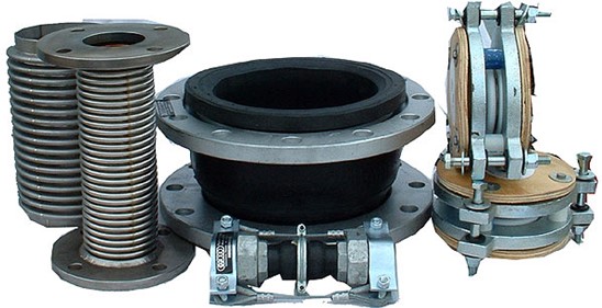
Introduction to Expansion Bellows
In a piping system a Expansion joints alternately known as Bellows are like sealed springs. Sealed because it is required to contain the fluid pressure which is flowing through it and spring because it is required to respond to the movement of the connected piping without offering appreciable stiffness to the piping system.
An expansion joint/bellow element employed in a piping system is an assembly of generally more than one convolute in series. The convolutes are designed strong enough to withstand the internal pressure of the system, at the same time the typical contour of the convolute assembly allow sit to flex under thermal movement of the connected piping. As a result of this extreme flexibility the expansion joint / bellow as such is highly incapable of absorbing any longitudinal loads by its own,thereby requiring external attachments to transfer these longitudinal loads to its connected piping for maintaining the overall stability of the piping system under question.

Expansion joints
COMMON TYPES OF EXPANSION JOINTS ARE:
- Simple Expansion Joint
- Universal Expansion Joint
- Pressure Balanced Expansion Joint
- Hinged Expansion Joint
- Gimbal Expansion Joint
Application of Expansion Bellows:
The Bellows are generally employed in a piping system in one of the following situations:
- When the space constraints do not permit providing adequate flexibility by conventionalmethods (e. g. expansion loops etc.) for maintaining the system stresses withinacceptable limits.
- When conventional solutions (e.g. expansion loops etc.) create unacceptable processconditions (e.g. excessive pressure drop).
- When it is not practical to limit the piping induced loads on the terminal nozzles of theconnected equipment within admissible limits by conventional methods.
- When the equipment such as Compressors, Turbines, Pumps etc. necessitate isolatingthe mechanical vibrations from being transmitted to the connected piping.
EXPANSION JOINT PRESSURE THRUST:
The end anchors in a piping system employing a Bellow requires special considerations owing the large imbalance axial force generated due to internal system pressure acting on the bellow convolutes. At the same time the inherent weakness of the Bellow to transfer the longitudinal force across its ends.
It is therefore imperative that a proper assessment of the imbalance Pressure Thrust of the Bellow and its effects on the piping end terminals be evaluated prior to using the Bellow on a piping system of large diameter and sizable internal pressure.
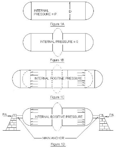
To understand the above phenomena let us consider a straight length of pipe of internaldiameter D capped at its both ends and subject to an internal pressure P (refer Fig.-1Abelow). The longitudinal Pressure Force acting at each capped end is:
Pf = πPD 2 / 4

Assessment of expansion joints
The above longitudinal force is carried in tension in the Pipe wall and the system remainsstable with the opposite and equal force acting at the capped end balancing each other. Nowlet us introduce a Bellow in the middle of the above pipe section (refer Fig 1B). Since the above Bellow does not have any appreciable longitudinal stiffness it will tend to straighten outas shown in Fig 1C below resulting into rapture of the convolutes. It is therefore necessary toprovide end anchors (refer Fig 1D below) to counter the pressure force acting at the endsand thereby stopping the bellow convolute from flattening. The magnitude of above force willbe combined longitudinal force acting at the Bellow inside diameter and the imbalancepressure thrust acting on the side-wall, of the convolute.
The net Pressure Thrust to be absorbed by the End Anchors, due to incorporation of the bellow in a straight pipe line, therefore it based on the Mean Diameter of the bellow and isgiven by
pπDm 2 / 4 where :
Dm = Mean Diameter of the bellow
P = System internal pressure.