Introduction:
Steam is perhaps one of the most efficient mode of energy transportation in the present times in Process Industry. However it has a potential of becoming highly inefficient if certain aspects associated with its handling are not appropriately addressed in the design of steam network.
The aspects, which are of particular concern with respect to efficient and safe design of steam network, are:
- The rapidness of evacuation of air or non-condensible gases from the steam network.
- The efficiency of heat transfer mechanism, which is directly related to the mode of heat transfer (i.e. latent heat or sensible heat)
- The integrity of system design under the influence of slug forces due the phenomena of Water Hammer, essentially resulting from accumulation of Condensate.
Why a Steam Trap?
The answer to all above concerns related to Steam Network design, is obviously an automatic device which can differentiate between the condensate and the air/ non-condensible gases (present in the system during initial startup) from the steam, to be able to selectively and efficiently discharge the air/ non-condensible gases and condensate from the system, at the same time to disallow the steam from escaping from the system.
Steam Trap is some such automatic draining device, which satisfies all above functional requirements in terms of discharging the condensate at the required flow rate under varying inlet and back pressure conditions, at the same time allowing a rapid evacuation of cool air/non-condensible gases from the system.
Effect of Poor Venting of Steam Network:
Unlike the other piping systems employed in handling liquids, the operating efficiency of the heat transfer equipment using steam as a heating medium is severely hit by the presence of initial air (or any other non-condensible gas) resulting from a poorly vented piping system across the equipment. Consequentially longer than designed time for attaining the required temperature which could slow down the production or sometimes may even affect the qualityof the product due to uneven temperature distribution across the heat exchanger. The graph below (refer Figure-1, Exhibit 34.1) shows the reduction in temperature due to different percentage of air in the steam.
Needless to say that the steam trap employed in such applications must primarily initially beable to vent out the trapped air of the piping system as quickly as possible to disallow the same to get mixed with the steam.
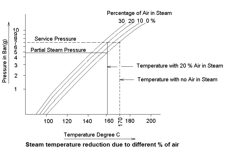
Figure-1 (Exhibit 34.1) Steam temperature deduction
In summary the trapped air/ non-condensible gases must be purged out of the system through an efficient built-in vent provided in the steam trap for following reasons:
- On start up the steam can fill into the system only fast as the air is vented out of it.
- An air steam mixture has a temperature well below the steam temperature (at thecorresponding pressure) lowering the heat transfer efficiency.
- Air is an insulator and clings to the internal surface of the pipe or shell causing slow anduneven heat transfer.
- The non condensible gases could dissolve in the condensate to form acids (e.g. carbonicacid) which may attach the material of construction of the piping/ equipment.
Effect of Condensate Accumulation:
As shown in the sketch below (refer Figure-1, Exhibit 34.2) the condensate accumulating on the bottom surface of the horizontal pipe, is swept along by the velocity of the steam passing over it. As steam approaches to high velocities the condensate gradually tends to form a solidslug of incompressible water, also flowing with almost the same velocity as that of the drivingsteam. When this water slug is suddenly stopped by any obstruction in the flow passage suchas bends, valves, fittings etc there is a sudden loss of momentum that it possessed while inmotion , resulting into a pressure wave (surge) which could produce momentary forces of very large magnitude (i.e. water hammer effect) and could cause damage to the piping system.
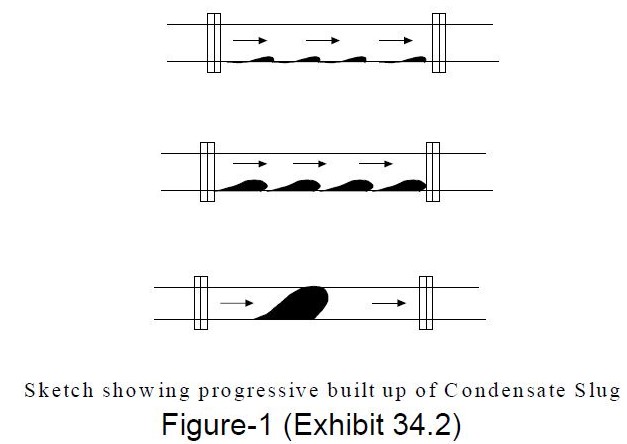
Condensate slug
A trap is therefore required on typically following locations where Condensate is likely to get formed.
1. Steam Distribution Headers:
- Where self-draining of the condensate is intercepted by vertical risers/ loops.
- At low points and at approximately every 50 – 60 Mts. of distance on horizontal pipe.
- Ahead of all possible Dead Ends (e.g. shutoff valves on bypass lines)
2. Steam Tracing/ Jacketing Service:
- At the steam supply manifolds for feeder lines.
- At the condensate collection manifolds.
3. Steam Operated Equipment:
- Ahead of Humidifier, Pumps and Turbines etc.
- Condensate outlet from the Equipment using steam (e.g. Condensers, Coils, Heaters, Drier etc.)