1. Introduction
Piping Engineer will be responsible for layout and floor space occupied by the shelter based on input from compressor vendor. Mechanical (Rotating) Engineer will be responsible for determining height of shelter as well as the type and capacity (SWL) of the crane. Piping Engineer and Mechanical (Rotating) Engineer will provide respective inputs to Civil Engineer for structural design. Mechanical (HVAC) shall be responsible for advising on the type of cladding (roof and sides) with type of insulation, if any, especially for closed shelters. They shall also advise requirements of any roof ridge ventilators (natural or forced draft) in case of closed shelters.
2. Shelter Description
2.1 Shelter Layout
When the compressor is covered (partially or totally enclosed by a shelter), many elements determine how the layout and orientation of the compressor and shelter must be planned and executed. Factors to be considered are:
- General arrangement of compressor
- Operation
- Maintenance
- Safety
Above factors are described below:
2.1.1 General arrangement of compressor
The general arrangement of the compressor is provided by the Vendor. The shelter shall accommodate the compressor and all its auxiliary units, including the supporting arrangements. It shall contain foot print area of supporting structure/foundation in plan and total envelop of machines in elevation. Some auxiliary units like the lube oil cooler may be placed outside the shelter.
2.1.2 Operation
Plant operations personnel need adequate space to walk safely around the machine.
They must have clear access to see and operate the valves, instruments, gauges, switches, lights, etc. on the machine and control panels. For this purpose, there needs to be:
- Identification and planning of operational area required for various components.
- Provision of operational clearances and clear passage for operating personnel.
Depending on the type of compressors, they may be either grade installed or table top installed. Compressors having top nozzles will be generally grade installed and compressors having bottom nozzles will be generally table top installed.
In case of table top installation top level of operating floor around compressor generally matches with top of supporting foundation/structure of compressor. Main access into the shelter is generally accomplished through a suitable door opening in the side cladding. Access to the elevated operating floor is by stairways provided inside the shelter. Additional stairways to drop-down area (refer paragraph below) may be provided to enable operation and maintenance personnel to get access to drop-down zone as well as area under operating floor.
2.1.3 Maintenance
All principal components to be removed during major maintenance must be able to be lifted by travelling crane/mobile crane and removed from building. The handling facility shall be designed to handle the heaviest single part of the compressor which is required to be removed for maintenance. Following handling facilities for component removal are generally considered:
- Permanent handling facility – EOT crane (Electrically operated travelling crane) or HOT crane (Hand operated travelling crane).
- Temporary handling facility – Mobile crane with provision of removable panel in roof of enclosure.
Drop-down area: In a totally enclosed building, where all compressor maintenance is generally handled by travelling crane, operating floor stops one bay before one of the gable end to make provision for drop down zone for maintenance. Common drop-down area may be provided for all compressors in a shelter provided that the movement of lifted object does not pass over running systems. Alternatively, individual drop-down areas may be provided. Mobile equipment/ pick-up truck is given access to this area through suitable sized door-way with rolling shutter in gable or side cladded walls for removal of components. Dimension of rolling shutter should be min 5500mm high and 3000mm wide to permit entry of mobile crane/truck.
Crane maintenance platforms: For maintenance of long travel and trolley (cross travel) of EOT/HOT cranes, maintenance platforms are generally provided at top of crane girder level, as per factory rules of relevant country. Access to these platforms is provided by cage ladders suitably located so that there is safe and unrestricted access to the ladders.
2.1.4 Safety
Shelter must have easy access throughout, and in case of closed shelters, sufficient ventilation as protection from potentially dangerous gas leaks, and sufficient number of doors and stairways in event of an emergency.
For further details on the types of compressors and their layout requirements (including auxiliary units) refer document no.PEC-EN-GDE-L-09288(Can you put the link of compressor piping at this location), Design Guidelines for Gas Compressor Piping.
2.2 Shelter Types
The design and type of the shelter depends upon the climatic conditions.
- Moderately warm climate without significant rainfall:
Under this climatic condition the shelter can be partially covered by providing cover to entire roof and side cladding on all four sides extending up to 2.0 m (maximum) from eaves level. This provides protection against direct sunlight and rainfall.
- Warmer climate without significant rainfall:
In this case entire roof along with all sides of the shelter needs to be covered. Side cladding on all sides starting from the eaves level shall terminate around 2.5m above floor level. This type of covering blocks sunlight for most of the day while allowing cooler breeze to pass through the structure.
- Climate with significant rainfall:
Fully covered shelter as described above is suitable for such climatic condition.
- Severely cold climates:
Totally enclosed shelters are provided under this climatic condition.
- Shelter Lighting and insulation:
In a closed shelter, besides the electrical lighting, natural daylight for work spaces inside can be considered. Civil/Architectural along with HVAC can work out the area of translucent sheeting in the side claddings and the roofing required as per the local Building Codes/Factory regulations.
The use of double skin sandwich panels and/or insulation may be considered for the cladding if specifically required in order to cater to safety (to act as fire wall), HVAC (to prevent heat loss) and acoustic (to maintain the noise level at acceptable limit in the outside environment) aspects.
2.3 Sizing of Shelter Elevation
Appendix 1 demonstrates how to size the height of a shelter, regardless of type of machines used. Sizing methodology is described in following paragraphs.
2.3.1 Operating floor elevation
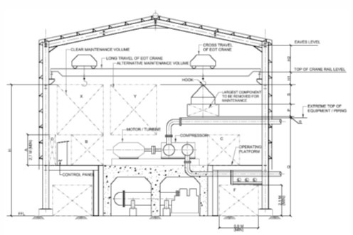
Operating floor elevation is established by making all standard allowances around and above equipment and providing usual head room below all horizontal pipe runs and conduits as shown by blocks E and F.
2.3.2 Shelter Width
Width of shelter is established by first allowing space for supporting foundation block/structure of largest compressor train. There must be adequate room for operation and maintenance in front of the compressor (including its auxiliaries and associated piping) as shown by block C. Similarly, on the driver (motor or turbine) side, there shall be sufficient room for maintenance as shown by block B. Any control panel mounted on operating floor must have sufficient rear space for operation as shown by block B, as well as access space at rear side for maintenance shown by block. Enough space shall be planned to isolate the compressor foundations from the shelter foundations.
2.3.3 Shelter elevation
Shelter elevation is established by considering following criteria:
- Size of clear maintenance volume (shown as X and Y): This volume must accommodate the single largest piece to be maintained at a minimum elevation above all operating floor requirements, shown as clearance A.
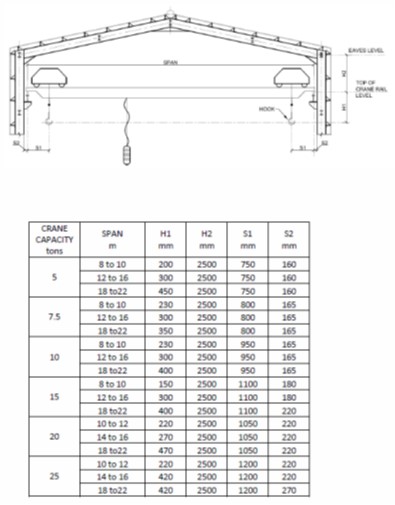
- Crane clearance: For shelter with overhead travelling crane, following dimensional data are necessary to evaluate height up to eaves level of shelter:
a) Maximum hook height (H) from grade/finished floor level,
b) Distance (H1) of top of crane rail level (on crane girder) with respect to highest hook position.
c) Allowable height (H2) of eaves level from top of crane rail.
The maximum hook height from ground is determined by:
H = P + Q + R + S
Where H = Maximum hook height
P = Maximum vertical dimension of component to be removed
Q = Maximum vertical dimension of any obstruction (machine, piping, etc.) encountered during handling of component by EOT/HOT crane.
R = Vertical clearance between obstruction and component to be removed
S = Vertical space occupied by slings, shackles, spreader bar, etc.
Dimensions H1 & H2 are to be adopted from crane clearance data from supplier of
EOT/HOT crane and depend upon capacity of crane and span of long travel (c-to-c distance of crane rail). A typical sample of crane clearance data is shown in
Appendix 2 for reference and for initial planning/sizing purpose when supplier data is not available.
Dimension H2 shall be suitably adjusted to accommodate any HVAC ducts running above the crane.
Annexure 1: Shelter height sizing diagram
Annexure 2 : Typical crane clearance data
|
CRANE |
SPAN |
H1 |
H2 |
S1 |
S2 |
|
5 |
8 to 10 |
200 |
2500 |
750 |
160 |
|
12 to 16 |
300 |
2500 |
750 |
160 |
|
|
18 to 22 |
450 |
2500 |
750 |
160 |
|
|
7.5 |
8 to 10 |
230 |
2500 |
800 |
165 |
|
12 to 16 |
300 |
2500 |
800 |
165 |
|
|
18 to 22 |
350 |
2500 |
800 |
165 |
|
|
10 |
8 to 10 |
230 |
2500 |
950 |
165 |
|
12 to 16 |
300 |
2500 |
950 |
165 |
|
|
18 to 22 |
400 |
2500 |
950 |
165 |
|
|
15 |
8 to 10 |
150 |
2500 |
1100 |
180 |
|
12 to 16 |
300 |
2500 |
1100 |
180 |
|
|
18 to 22 |
400 |
2500 |
1100 |
220 |
|
|
20 |
10 to 12 |
220 |
2500 |
1050 |
220 |
|
14 to 16 |
270 |
2500 |
1050 |
220 |
|
|
18 to 22 |
470 |
2500 |
1050 |
220 |
|
|
25 |
10 to 12 |
220 |
2500 |
1200 |
220 |
|
14 to 16 |
420 |
2500 |
1200 |
220 |
|
|
18 to 22 |
420 |
2500 |
1200 |
270 |