1.0 Introduction to Column Piping
Study for the column piping should start after complete understanding of the following document:
a) Technical specification of the column
b) P&ID
c) Unit Plot Plan
d) Basic Engineering document highlighting the specific process requirement, platform requirement and guidelines for the general arrangement of piping around the column.
e) Details of internal arrangements e.g. for packed type – the packing height, packing support and manhole / hand hole locations, and for tray type – the nos. of tray, type of tray, downcomer location, manhole location etc.
f) Instrument data sheet.
g) Line list with operating / design conditions of the fluid.
Some understanding of the process function will facilitate the column piping study to meet the requirements of operation, maintenance, safety and the aesthetics. Various types of column with their varying functions are in use for refinery and Petrochemical industry.
Generally they are distinguished based on the specific operation for mass transfer viz. Distillation, Absorption – stripping or Fractionation etc.
2.0 Distillation Column Piping
The distillation is separation of the constituents of a liquid mixture via partial vaporization of the mixture and separate recovery of vapour and residue.
Various kinds of devices called plates or trays are used to bring the two phases into intimate contact. The trays are stacked one above the other and enclosed in a cylindrical shell to form a Distillation Column.
The feed material, which is to be separated into fractions, is introduced at one or more points along the column shell.
Due to difference in gravity between liquid and vapour phases, the liquid runs down the column, cascading from tray to tray, while vapour goes up the column contacting the liquid at each tray.
The liquid reaching the bottom of the column is partially vaporized in a heated reboiler to provide reboil vapour, which is sent back up the column. The remainder of the bottom liquid is withdrawn as the bottom product.
The vapour reaching the top of column is cooled and condensed to a liquid in the overhead condenser. Part of this liquid is returned to the column as reflux to provide liquid overflow and to control the temperature of the fluids in the upper portion of the tower. The remainder of the overhead stream is withdrawn as the overhead or distillate product.
The typical distillation process tower is illustrated in Fig.1 and crude distillation of products across temperature range is illustrated in Fig.2
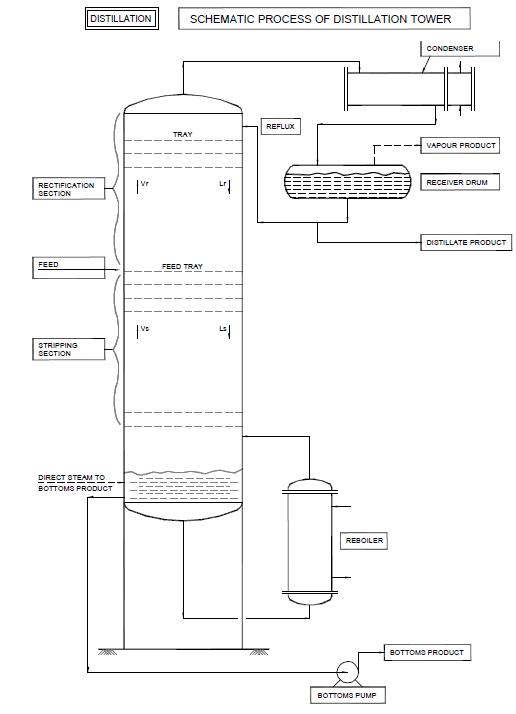
Fig 1 – Schematic – Process of Distillation Tower
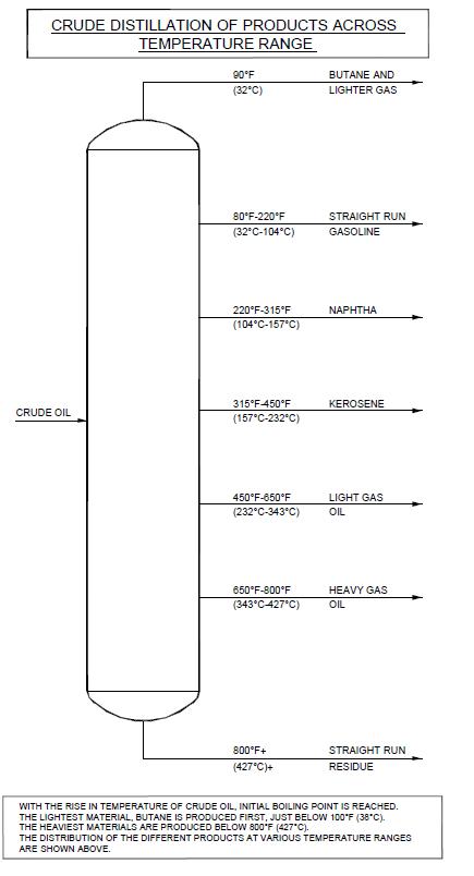
Fig 2- Crude Distillation of Products Across Temperature Range
2.1 Absorption And Stripping
Many operations in petrochemical plants require the absorption of components from gas streams into lean oils or solvents.
The resultant rich oil is then stripped or denuded of the absorbed materials. The greatest use of this operation utilizes hydrocarbon materials, but the principles are applicable to other systems provided adequate equilibrium data is available.
A typical flow diagram of absorption-stripping system for hydrocarbon recovery from gaseous mixture is illustrated in Fig. 3.
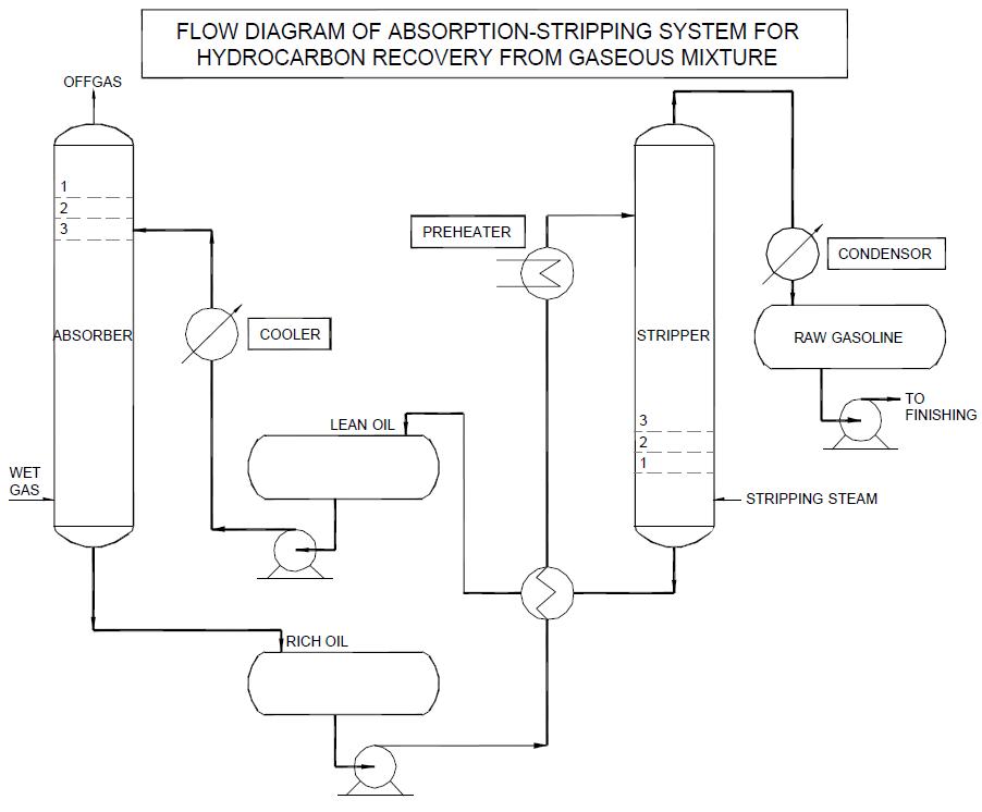
Fig 3- Flow Diagram of Absorption-Stripping System for Hydrocarbon Recovery from Gaseous Mixture
2.2 Fractional Distillation
A fractionation column is a type of still. A simple still starts with mixed liquids, such as alcohol and water produced by fermenting grain etc. and by boiling produces a distillate in which the concentration of alcohol is many times higher than in feed. In petroleum industry, mixtures of not only two but a lot many components are dealt with. Crude oil is a typical feed for a fractionation column and from it, the column can form simultaneously several distillates such as wax distillate, gas oil, heating oil, naptha and fuel gas. These fractions are termed cuts.
The feed is heated in a furnace before it enters the column. As the feed enters the column, quantities of vapour are given off by flashing due to release of pressure on the feed.
As the vapours rise up the column, they come into intimate contact with down flowing liquid.
During this contact, some of the heavier components of the vapour are condensed and some of the higher components of the down flowing liquid are vaporized. This process is termed refluxing.
If the composition of the feed remains the same and the column is kept in steady operation, a temperature distribution establishes in the column. The temperature at any tray is the boiling point of the liquid on the tray. ‘Cuts’ are not taken from every tray. The P&ID will show cuts that are to be made, including alternatives. Nozzles on selected trays are piped and nozzles for alternate operation are provided with line blinds or valves.
The fractionator tower is illustrated in Fig.4.
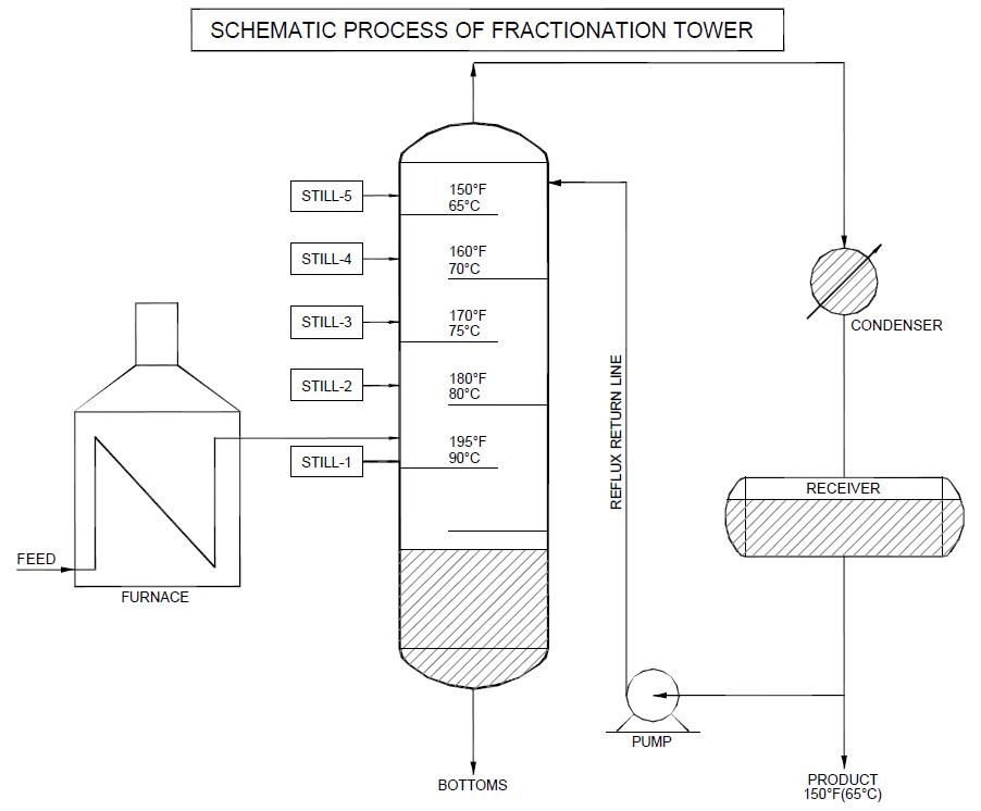
Fig 4- Schematic Process of Fractionation Tower
The typical vacuum tower and stripper is illustrated in Fig.5. Stripper is used to strip lighter materials from bottom of a main or a vacuum tower distilling crude bottom residue under vacuum.
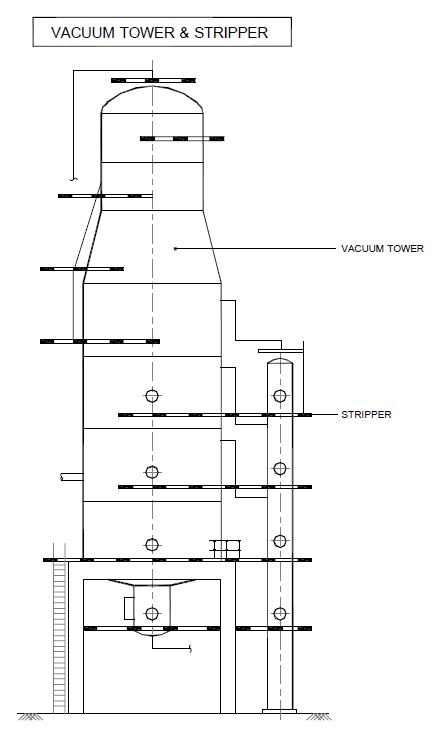
Fig 5- Vacuum Tower & Stripper
2.3 Columns based Internals
Columns based on internal details are often called as either Plate Columns or Packed Columns.
Plate Column:
The lighter hydrocarbons vaporize and flow up through the holes in the tray plate, making contact with the liquids on that tray.
Tray types are: Bubble Cap trays, Valve trays, Sieve trays
Bubble Cap Trays: Bubbling action effects contact. Vapour rises up through ‘risers’ into bubble cap, out through slots as bubbles into surrounding liquid on tray. Liquid flow over caps, outlet weir and downcomer to tray below.
Valve Trays: Commonly used valve trays are stamped out by big press and these trays come with small valves attached to them which allow vapour traffic.
Sieve Trays: Sieve trays are perforated flat plates. They are inexpensive for small diameter vessels but large diameter towers must have extensive supports for these trays. Sieve trays are used for heavy hydrocarbon fractionation.
All trays have foam on top of liquid. The height of the foam will vary with the process. Foam may rise a foot or more above the tray liquid.
Liquid-gas contacting is made effective through the above trays by cross-flow or counter flow.
In counter flow plates, liquid and gas utilize the same openings for flow, thus there are no downcomers.
Perforated plate with liquid cross flow (sieve plate) is the commonly specified tray.
These two types of flow is illustrated in Fig.8.
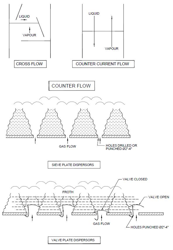
Fig 8 -Counter Flow (Sieve & Valve Plate Dispersors)
The two most commonly used types of tower viz. the trayed and packed arrangements are illustrated in Fig.6 and Fig.7 respectively.
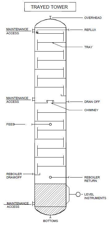
Fig 6- Trayed Tower
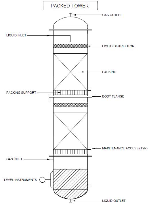
Fig 7- Packed Tower
3.0 Required Information for piping
The basic document listed shall be studied thoroughly for conceptual arrangement of piping around a column.
3.1 The basic layout and general engineering specifications describe:
- The minimum access, walkways, platforms width and headroom requirements.
- Handling facilities for tower internals, manhole covers, line blinds, relief valves.
- Maximum rise of ladders.
- Pipe-system requirements, such as open or closed relieving systems.
- Minimum line-size and required hose-stations.
- Access to valves and instruments.
3.2 Design Standards show:
- Details of ladder dimensions
- Ladder and platform position (Step through or side step landings)
- Toe-plate, handrail and safety-gate details.
3.3 P&ID and Technical specification of column provide :
- Process data showing interconnected equipment and piping.
- Pipe sizes and pipeline components.
- Steam tracing and insulation thickness.
- Tower elevations and differences in related equipment levels.
3.4 Plot Plan gives:
- The physical location of a column and its relationship to other equipment.
- Main access.
- Main pipe run or pipe rack.
- Location of pumps.
A typical cross-section of a piperack running through the tower area of a refinery type plant is illustrated in Fig.9.
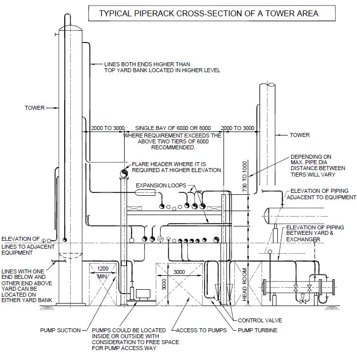
Fig 9- Typical Piperack Cross-Section of a Tower Area
A typical plan of equipments located in the refinery type of plants highlighting the maintenance access is illustrated in Fig.10.

3.5 Instrument standard shows:
- The location of instrument connections to tower for gauges, level controllers and level alarms.
- Location of pressure and temperature connections without orientation.
- The instrumentation systems around the tower are depicted in the P&ID.
3.6 Fabrication drawing / detail dimensional drg. of column provides :
- Diameter and height of column.
- Details and dimensions of internals.
- Manhole
- Process-piping connections in elevation (without orientation)
- Drum, pump, exchanger drawings giving details of adjacent process equipment or equipment supported on column itself.
An integrated piping study should be developed from the above information.
The piping study should take care of all the general recommendations of piping arrangement around the column and its related equipment and facilities as illustrated in Fig.11
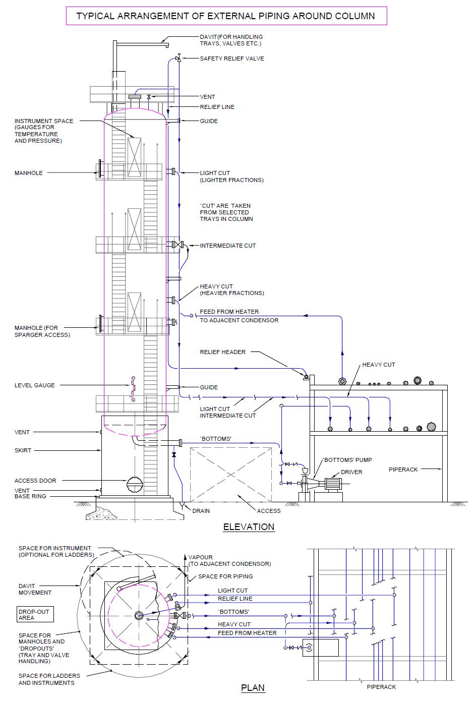
Fig 11- Typical Arrangement of External Piping Around Column