1.0 Introduction to Elbows:
Elbows are used for changing direction in piping system.
2.0 Elbow Angle:
An elbow angle is defined as an angle by which the flow direction deviates from its original direction.
As shown in Figure - 1 & 2, the flow deviates by an angle θ from its original direction and hence elbow angle in this case is θ.
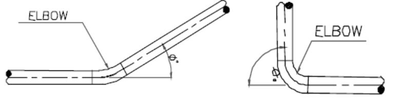
Elbow angle
An elbow angle can be anything greater than 0 but less or equal to 90°. A change in direction greater than 90° at a single point is not desirable. Usually, we use 45° and 90° elbows while making piping layouts.
Refer Fig. - 3. Pipe direction is changing at point A using an elbow and again the direction is changing at point G using another elbow.
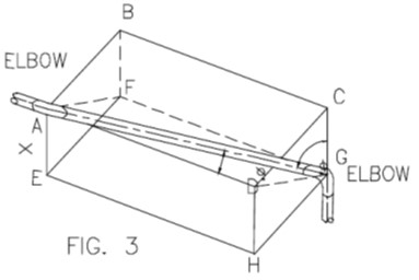
In order to work out elbow angle at A, it is essential to consider a plane which contains arms of the elbow. If there had been no change in direction at point A, the pipe would have moved along line AD but pipe is moving along line AG. Plane AFGD contains lines AD and AG and elbow angle θ is marked which denotes the angle by which the flow is deviating from its original direction.
Considering right angle triangle AGD,
tan θ = √(x2 + z2) / y
Similarly elbow angle at G is given by:
tan θ1 = √(y2 + z2) / x
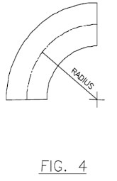
3.0 Elbow Radius:
For a smooth change in direction, elbows or bends are available in various radii. These radii are expressed in terms of pipe nominal size expressed in inches. Elbows are available in two radii,
a. Long radius elbows (Radius = 1.5D)
b. Short radius elbows (Radius = 1.0D)
where D is nominal pipe size in inches.
For radius more than 1.5D, pipe bends are used and these can be made to any radius.
However, 3D & 5D pipe bends are most commonly used. Usually in chemical, petrochemical
& refinery plants, long radius elbows are widely used. Pipe bends are preferred where pressure drop is of a major consideration. Use of short radius elbows should be avoided as far as possible due to abrupt change in direction causing high pressure drop.
Elbow Radius
4.0 End Connections:
The following types of end connections are available for connecting elbow/bend to pipe.
• Socket welded
• Butt welded
• Screwed
• Flanged
A. Socketed Welded Elbows:
• Pipe is connected to socket welded elbow as shown in Fig. - 5, by having a fillet weld.
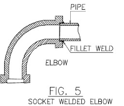
Socketed Welded Elbows
• Socket welded elbows are available upto 2” nominal size. However, in UIL, our practice is to use these elbows upto 11/2” size only.
• Dimensions of socket welded elbows are as per ASME B16.11
• Since there is possibility of fluid getting entrapped between pipe O.D and socket I.D., this may cause corrosion called crevice corrosion. Thus use of socket welded fittings should be avoided for services where corrosion/erosion is of great concern.
• Fillet welds are examined by using liquid dye penetrant or Magnetic particle inspection method. No radiography is possible for checking soundness of these welds.
• Since socket welded joints cannot be radiographed, these fittings are not recommended for critical services handling hazardous or highly inflammable fluids. For such services butt welded fittings are preferred.
• Socket welded fittings are forged and applicable material standards are as follows:
ASTM A105 (Forged Carbon Steel)
These fittings are suitable for welding to all carbon steel pipes.
ASTM A182 (Forged Alloy Steel and Stainless Steel Fittings)
Under ASTM A182 several grades are available depending upon chemical composition.
Selection would depend upon pipe material connected to these fittings. Fitting material should have same chemical composition as that of pipe.
Some of the grades available under ASTM A182 and corresponding connected pipe material specification are listed below:
GRADE PIPE MATERIAL SPEC
F11 : ASTM A335 P11
F22 : ASTM A335 P22
F304 : ASTM A312 Gr.TP 304
F304L : ASTM A312 TP 304L
F316 : ASTM A312 TP 316
F321 : ASTM A316 TP321
ASTM A350 (Forged carbon and low alloy steel fittings for low temperature services)
Under ASTM A350, several grades are available depending upon chemical composition & tensile properties.
• Fittings conforming to ASME B16.11 are designated as Pressure class 2000, 3000 and 6000 fittings for threaded and Pressure class 3000, 6000 and 9000 for socket welded ends.
This designation identified the fittings with their ratings as shown below:
(Refer Table 2, ASME B 16.11)
|
Pressure |
Type |
Pipe used for Rating Basis Schedule No./Wall designation |
|
2000 |
Threaded |
80 / (XS) |
|
3000 |
Threaded |
160 /- |
|
6000 |
Threaded |
— / XXS |
|
3000 |
Socket-Welding |
80 / (XS) |
|
6000 |
Socket-Welding |
160 /- |
|
9000 |
Socket-Welding |
— / XXS |
The above does not restrict the use of pipe of thinner or thicker wall with fittings. However, when thinner pipe is used, its strength may govern and when thicker pipe is used, the strength of the fitting governs the rating.
B. Butt Welded Elbows:
• Pipe is connected to butt welded elbow as shown in Fig. 6 by having a butt-welding joint.
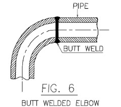
Butt Welded Elbows
• Butt welded fittings are supplied with bevel ends suitable for welding to pipe. It is important to indicate connected pipe thickness schedule while ordering. All edge preparations for butt welding to conform to ASME B16.25.
• Dimensions of butt welded elbows are as per ASME B16.9. This standard is applicable for carbon steel & alloy steel butt weld fittings of NPS 1/2” through 48”
• Dimensions of stainless steel butt welded fittings are as per MSS-SP-43. Physical dimensions for fittings are identical under ASME B16.9 and MSS-SP-43. It is implied that the scope of ASME B16.9 deals primarily with the wall thicknesses which are common to carbon and low alloy steel piping, whereas MSS-SP-43 deals specifically with schedule 5S & 10S in stainless steel piping.
• Dimensions for short radius elbows are as per ASME B16.28 in case of carbon steel & low alloy steel and MSS-SP-59 for stainless steel.
• Butt welded fittings are usually used for sizes 2” & above. However, for smaller sizes up to
11/2” on critical lines where use of socket welded joints is prohibited, pipe bends are used.
These bends are usually of 5D radius and made at site by cold bending of pipe.
Alternatively, butt welded elbows can be used in lieu of pipe bends but usually smaller dia lines are field routed and it is not possible to have the requirement known at initial stage of the project for procurement purpose. So pipe bends are preferred. However, pipe bends do occupy more space and particularly in pharmaceutical plants where major portion of piping is of small dia. and layout is congested, butt welded elbows are preferred.
• Butt welded joints can be radiographed and hence preferred for all critical services.
• Material standards as applicable to butt welded fittings are as follows:
ASTM A234:
This specification covers wrought carbon steel and alloy steel fittings of seamless and welded construction. Unless seamless or welded construction is specified in order, either may be furnished at the option of the supplier. All welded construction fittings as per this standard are supplied with 100% radiography. Under ASTM A234, several grades are available depending upon chemical composition. Selection would depend upon pipe material connected to these fittings.
Some of the grades available under this specification and corresponding connected pipe material specification are listed below:
| GRADE | PIPE MATERIAL SPEC |
| WPB : | ASTM A53 Gr A/B, A106 Gr A/B |
| IS 1239, IS 1978, IS 3589 | |
| WPC : | ASTM A106 Gr.C |
| WP11 : | ASTM A335 P11 |
| WP22 : | ASTM A335 P22 |
ASTM A403:
This specification covers two general classes, WP & CR, of wrought austenitic stainless steel fittings of seamless and welded construction.
Class WP fittings are manufactured to the requirements of ASME B16.9 & ASME B16.28 and are subdivided into three subclasses as follows:
WP – S Manufactured from seamless product by a seamless method of manufacture.
WP – W These fittings contain welds and all welds made by the fitting manufacturer including starting pipe weld if the pipe was welded with the addition of filler material are radiographed. However no radiography is done for the starting pipe weld if the pipe was welded without the addition of filler material.
WP-WX These fittings contain welds and all welds whether made by the fitting manufacturer or by the starting material manufacturer are radiographed.
Class CR fittings are manufactured to the requirements of MSS-SP-43 and do not require non-destructive examination.
Under ASTM A403 several grades are available depending upon chemical composition.
Selection would depend upon pipe material connected to these fittings. Some of the grades
listed below:
| GRADE | PIPE MATERIAL SPEC | ||
| WP | 304 | WP 304S : | ASTM A312 TP304 |
| WP304W : | |||
| WP304WX : | |||
| CR | 304 | ||
| WP | 304L | WP304LS : | ASTM A312 TP304L |
| WP304LW : | |||
| WP304LWS : | |||
| CR | 304L | ||
ASTM A420:
• This specification covers wrought carbon steel and alloy steel fittings of seamless & welded construction intended for use at low temperatures. It covers four grades WPL6, WPL9, WPL3 & WPL8 depending upon chemical composition. Fittings WPL6 are impact tested at temp - 50° C, WPL9 at -75° C, WPL3 at -100° C and WPL8 at -195° C temperature.
• The allowable pressure ratings for fittings may be calculated as for straight seamless pipe in accordance with the rules established in the applicable section of ASME B31.3.
• The pipe wall thickness and material type shall be that with which the fittings have been ordered to be used, their identity on the fittings is in lieu of pressure rating markings.
C. Screwed Elbows:
• These are usually used for Galvanised piping where all joints are screwed type. Fittings used are also galvanized on such lines.
• Following standards are usually adopted for galvanized screwed fittings.
IS 1239 Part II
ASTM A105 or ASTM A181 Class 60 forged & galvanized and dimensions conforming to ASME B16.11.
• Usually we do not use fittings conforming to IS 1239 part II because the same are not forged and get cracked while tightening. Forged fittings having dimensional standard conforming to ASME B16.11 are preferred. For pressure rating of these fittings, refer Paragraph on pressure ratings of socket welded fittings.
• Screwed joints are made by using teflon tape for sealing.
• There is always a possibility of leakage through screwed joints. These type of joints are not recommended for hazardous fluids.
• Sometimes, seal welding is done for screwed joints in order to avoid leakage. However screwed connection at instruments shall not be seal welded.
• Pipe threads are usually as per IS554 taper.
D. Flanged Elbows:
• Usually flanged elbows are used on cast-iron piping. Cast steel flanged elbows with liner are used to some extent for lined piping such as carbon steel-PTFE lined (Refer chapter on lined-piping)
• Following standards are usually adopted for flanged elbows & other fittings:
ASME B16.1 (Cast Iron Pipe Flanges and Flanged Fittings; Classes 25,125 and 250)
ASME B16.5 (Pipe Flanges and Flanged Fittings).
• As per ASME B16.1, cast iron fittings are available in classes 25, 125, 250. Based on pressure-temperature conditions, proper rating can be selected as per table 2 ASME B16.1. All ratings are dependent on the contained fluid and are the maximum non shock pressures at the tabulated temperature.
• All class 25 & 125 flanged fittings are furnished with flat face. All class 250 flanged fittings are furnished with 0,06 inch high raised face and finished in accordance with MSS-SP-6.
• The minimum material requirements for flanged cast iron fittings shall be as follows:
|
Rating |
Size |
Class of Iron |
|
25 |
All |
ASTM A126 Class A |
|
125 |
1″ - 12″ |
ASTM A126 Class A or B |
|
125 |
14″ & above |
ASTM A126 Class B |
|
250 |
1″ - 12″ |
ASTM A126 Class A or B |
|
250 |
14″ & above |
ASTM A126 Class B |
The equivalent IS material usually used is IS 210 Gr. 220.
E. Mitre Elbows:
• These are usually used for low pressure, low temperature non critical services having 14” inches and above. They are economical as compared to elbows in higher sizes and hence preferred.
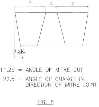
• Mitre bends are usually fabricated at site out of pipe by cutting and re-welding spools as shown in Fig. 7. The Figure is for 5 piece 4 weld mitres. The change in direction at every weld is 22 1/2 °. We may also have 4-piece 3-weld mitre where change in direction at every weld would be 30°. Usually 5 piece 4 weld mitres are preferred in order to have smooth flow.

• Usually effective radius of mitre-bend, defined as the shortest distance from the pipe centre line to the intersection of the planes of adjacent mitre joints is 1.5D where D is the nominal pipe size in inches. However, one can select any other radius if called for.
• It is recommended to fabricate mitre bends after knowing length of Arm-1 & Arm-2 up to next weld (Refer Fig. 7). So as to avoid two additional welds.
• Because of high stress intensification factor they are not recommended on high temperature lines.
• Pressure-temperature rating for mitre bend is not the same as for pipe and in order to withstand same pressure-temperature conditions as applicable to pipe, a higher thickness is required for mitre bend.
As per ASME B31.3 (Cl. 304.2.3), the maximum allowable internal pressure shall be the lesser value calculated from equation given below :
These equations are not applicable when θ exceeds 22.5°
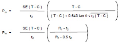
Where
Pm = Maximum allowable internal pressure for mitre bend.
T = Minimum Miter Pipe wall thickness.
C = Sum of mechanical & corrosion allowances.
R1 = Effective radius of mitre bend.
r2 = Mean radius of pipe using nominal wall thickness.
S = Allowable stress of material at the given temperature.
E = Quality factor as applicable to pipe used for mitre bend.
θ = Angle of mitre cut or 1/2 the angle of change in direction at mitre joint.
Thickness ‘T’ used in above equations shall extend a distance not less than ‘M’ from the inside crotch of the end mitre welds where,
M = larger of 2.5 (r2 × T) 0.5 or tan θ (R1 - r2).
Usually extra thickness is available in pipe used for low pressure services and it is possible to use the same pipe for making mitre bends. However a check is always required.
• An angular offset of 3° or less does not require design consideration as a mitre bend.
Very good reference!
Hi.is anyone knows dimension of elbow over 50 inhes?thanks
Hi there,
ASME B16.9 is dimensions standard for Factory-Made Wrought Buttwelding Fittings which covers sizes from ½” to 48”. This standard covers elbows.
MSS SP 75 is other standard for Specification for High-Test, Wrought, Butt-Welding Fittings, refer Table 4 Dimensions of Long-Radius Elbows from ½” to 60”.
Note:
For 90deg long radius elbow, Center to end can be calculated as 1.5 X D
Eg: For 50” 90deg long radius elbow= 1.5 X 50 = 75” or 1905mm
For 45deg long radius elbow, Center to end can be calculated as 1.5 X D X tan 22.5
Eg: For 50” 45deg long radius elbow= 1.5 X 50 X tan 22.5 = 31” or 787.4mm
Hope this helps.
AJ