Globe Valves:
A globe valve is used for regulating flow in a pipeline. A globe valve consists of a movable disk-type element and a stationary ring seat in a generally spherical body.
The gradual change in spacing between the disk and seat ring gives the globe valve good throttling ability.
Globe Valves are available with a variety of bonnet types, body and trim materials and stem packing in addition to a broad range of pressure classes, and end connections including extended bodies.
 Globe valve |
 Globe valve |
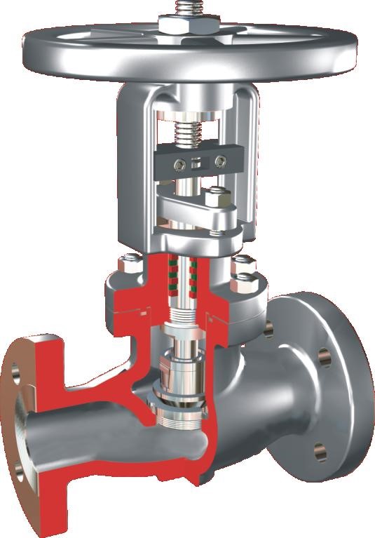
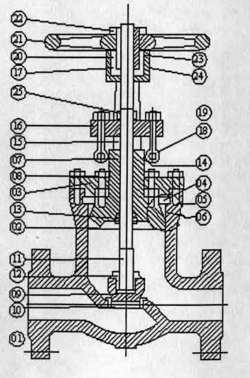
A typical globe valve has the following parts:
- Body
- Bonnet
- Yoke
- Backup Ring
- Thrust Ring
- Gasket
- Gland
- Stud and Nut
- Plug
- Seat Ring
- Spindle
- Plug Nut
- Back seat
- Clamp
- Gland Bush
- Gland Flange
- Yoke Sleeve
- Cross Bolt and Nut
- Eye Bolt and Nut
- Yoke Nut
- Hand Wheel
- Hand Wheel Nut
- Grub Screw
- Grease Nipple
- Anti-Rotation Device
Body:
The construction of the body differs from that of the gate valve. The body ports are arranged such that the flow is from the underside of the disk. Though the code specifies that the globe valves shall be designed suitable for installation in either direction of flow, the preferred direction of flow for globe valve shall be from under the disk. Normally the direction of flow is
cast or embossed on the valve body.
There are two types of port designs possible, the full port and the reduced port.
In the full port design the body ports shall be as large as practicable design considerations permit. However, in no case the net area of the bore through the seat of globe shall be less than 85% of the area of the actual pipe bore. In the reduced port design, the port diameter is normally one size less than that of the connected pipe.
Bonnet:
The body bonnet connection for the globe valve is the same as that of gate valves.
Disk:
The disk of the globe valves shall be:
- Flat faced type,
- Plug type, or
- Needle type
The flat faced type disks are used when the valve is to be used for the positive shut off service. For such valves, disk can be provided with an elastomer ring or facing which will ensure the same.
The needle type disk is used when finer flow control is to be achieved.
These disks can also be of contoured design as used in flow control valves. These are generally used for precise flow control applications. Bellow seal is the only way to achieve emission control in this type of valve.
The loose plug design allows the same to be renewable. When in the fully open position, the net area between the disk and seat shall be equal to the area through the seat.
The disk shall be either loose or integral with stem. The integral design is used mainly for the needle type of disc.
Stem:
In case of globe valves, the stems are always of rising design along with the hand wheel. The stem is provided with a disk nut at the lower end. The upper end is provided with a hand wheel screwed by stem nut.
Gland, Gland flange, Packing & Lantern:
Design and details same as that of gate valves.
Seat rings:
In case of globe valves of carbon steel, the hardfaced seats can be directly deposited on the body.
Yoke and Yoke bush:
The construction of the Yoke is the same as that of the gate valve. The Yoke sleeve of the gate valve is machine finished on all surfaces whereas that of the globe valve shall be screwed or fitted in the position and locked.
Hand wheel and Hand wheel Nut:.
Unlike in gate valve the hand wheel also rises along with the stem for globe valve. When used as a control valve, actuators are fixed so that the stem movement is effected through the same. In case of bellow sealed globe valves, the non rising hand wheel design is provided similar to that of gate valve. This is to ensure that the bellows are not subjected to torsion.
The above are the major design aspects of the globe valves and where comparison of the same with the gate valves as regards the material of construction, end connection etc. are concerned, the same shall be selected by the piping engineer based on the service of the line to which the valves are attached. The environment in which the valve is installed also will have to be considered while selecting the material.
There could be slight variation in design from manufacturer to manufacturer, but the basic design features as specified are not altered.