Introduction to Gate Valves
Gate valves (GV) are specifically used in isolation applications in various piping systems. And they operate in the fully opened or fully closed positions.
Like other isolation types of valves like ball valve, plug valve, piston valve, diaphragm valve, butterfly valve, pinch valve, gate valves are also isolation valves.
Gate valves are multi-purpose bi-directional shutoff valves for commercial and industrial applications. The shutoff action is achieved by moving the wedge in vertically up/down direction in the valve body, because of their ability to cut through liquids.
They are not recommended for regulation purpose as most of the flow change occurs near shutoff with a relatively high fluid velocity causing disk and seat wear and eventual leakage.
Gate Valves are available with a variety of bonnet types, body and trim materials and stem packings in addition to a broad range of pressure classes, and end connections including extended bodies.
Typical Gate valves has various parts which could be identified as
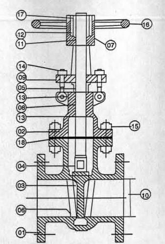
Gate Valves
| 1. Body | 10. Valve Port |
| 2. Bonnet | 11. Yoke Bush. |
| 3. Wedge | 12. Lantern |
| 4. Stem | 13. Back Seat Bushing |
| 5. Gland | 14. Gland eye bolts & nuts |
| 6. Seat ring | 15. Bonnet bolts & nuts |
| 7. Yoke | 16. Hand Wheel |
| 8. Packing | 17. Hand Wheel nut |
| 9. Gland Flange | 18. Bonnet Gasket |
Body:
The body in gate valves gets attached to the vessel or piping. The classification of the body could be done depending on the end connections as indicated earlier. Body could also be specified based on the material of construction of the same.
The wall thickness and end to end/face to face dimensions of the body shall be as per the Regulatory code to which it is designed.
The end flanges shall be integrally cast or forged with the body. It can also be attached by welding, if so specified. The end connection shall suit the rating specified. The flanged connection shall be to ASME B 16.5 or any of the flange standards.
The butt welding end connection shall be to ASME B 16.25 or any other end preparation required. The socket weld/screw connection shall be to ASME B 16.11 or any other equivalent standards. The body can have auxiliary connection such as drains, by-pass connections, etc.
Bonnet:
The bonnet is classified based on the attachment of the same to the body. The type of connections normally adopted are Bolted, Bellow sealed, Screwed-on, Welded, Union, Pressure sealed etc.
The bolted connection shall be flanged, male and female, tongue and groove or ring type joint. In low pressure rating valves, it may be flat faced. The bonnet gasket is selected to suit body bonnet connection. It can be corrugated or flat solid metal, corrugated or flat metal jacketed, asbestos filled, metal ring joint, spiral wound asbestos filled, flat ring compressed asbestos for low pressure application, Teflon or Teflon filled for corrosive applications.
The bellow sealed bonnets can be bolted or welded on to the body. These are selected for very critical services like the nuclear application and very high temperature and lethal services. The screwed-on bonnet is used for very low priority application and small sized valves.
Wedge:
This is the part which facilitates the service by its movement up and down. The type of wedges are classified as
• Solid Plain Wedge
• Solid Flexible Wedge
• Split Wedge
When solid disc is wedged into the rigid body seat and the valve undergoes temperature changes, the wedge gets jammed in the seat. Hence the flexible wedge and split wedge design is developed to overcome this difficulty.
Normally the solid plain wedge is referred as solid wedge and the split wedge is referred as flexible wedge. The design slightly alters with the manufacturers though the basis remains the same.
The flexible wedge design is followed for valve sizes 50 NB and above. Valves 40 NB and below are available in solid wedge design only. Flexible wedge design is superior as it will not get jammed during high temperature operations. The wedge material should be at least of the same quality as that of the body. In case of integral seat rings the wedge circumference is deposited with superior quality material. In smaller valves, the whole wedge will be manufactured out of superior material.
Stem:
The stem connects the hand wheel and the wedge for operations. The design can have rising stem and non rising stem. The stem is operated rotating the stem nut by hand wheel mounted at the top of the yoke. In the rising stem design, the stem moves up along with the wedge to open.
This is called the OS & Y ( Outside Screw and Yoke) type of design. In case of non rising stem the wedge moves up and down and the stem is stationary. This is called the inside screw design.
Normally, bar stock or forging are used for the construction of stem.
Gland, Gland flange, Packing and Lantern:
There are two types of gland designs possible, Single piece and Two piece. In two piece design, there will be gland flange and a follower. The follower will have a spherical end which facilitates proper aligning of follower and load on the packing. In Single piece, the gland and follower will be cast integral. This design is used mostly in low pressure valves. Normally gland follower will be of superior material than the gland flange. Gland flanges normally are made of carbon steel only. The glands are bolted to the bonnet with gland eye bolts.
The regulatory codes specify that the stuffing box should accommodate minimum six packing rings for class 150 valves. As regards higher rating valves, it should have lantern ring with five packing rings above and two packing rings below lantern. Lantern is not provided for class 150 valves. Lantern is provided for higher rating if required. When lantern is provided, the stuffing box shall be provided with two plugged holes. The material of lantern shall have corrosion resistance equal to that of the body.
Normally, the packing are of braided asbestos with suitable corrosion inhibitor. When special packing such as ‘Graphoil’ is used, the number of packing rings required will be more. To accommodate more packing rings, the length of gland is also modified. This design is called
the ‘Deep Gland’ design. This is used for the high temperature services. But this cannot satisfy the EPA’s fugitive emission standard of < 500 ppm threshold. Hence frequent LDASR will result in excessive expenditure.
Seat Rings:
There are two types of designs possible in seat rings. They are the integral and renewable. In case of renewable seat rings, it may be either threaded, rolled in or welded in. In case of integral seat rings, the seat material is weld deposited directly on to the valve body. The minimum hardness specified by the code for this material is 250 HB, with 50 HB minimum differential between body and gate seats, the body seat being harder.
The back seat arrangement is provided to repack the stuffing box when the gate is in fully open position. The stem shall have an integral conical or spherical backseat surface to seat against the bonnet backseat.
Yoke and Yoke Bush:
Yoke may be integral with or separate from the bonnet. When the yoke is integral, the stem nut should be removable without removing bonnet. The yoke should have the same material of construction as that of the shell. The Yoke bush is normally a Ni resist material. This is to prevent gauling of the stem as stem will normally be of a Nickel alloy.
Hand wheel and Hand wheel Nut:
The hand wheel is fixed to the stem by a threaded hand wheel nut. The arrow pointing the direction to open the valve will be marked with the word “open” or “close” or “shut” unless the size makes it impracticable. Valves shall be closed by turning the hand wheel in clockwise direction.
The material of construction of hand wheel shall be malleable iron, Carbon steel, Nodular iron or Ductile iron. Cast iron is not referred. The nut shall be of carbon steel or stainless steel.
When the installed position of the valve is such that the hand wheel is not accessible, then the hand wheels are replaced by chain wheels and the valve is operated with chains. For large diameter valve where the operating torque is high, gear arrangement is provided to facilitate operation. Mostly, bevel gear equipment is adopted. If remote operation of the valve is required, then this could be achieved through motor with switches. Proper selection of the drive unit should be done depending on the services.
Bolting:
Normally high tensile stud bolts are used for bonnet bolts and low carbon bolts for gland and yoke bolting. Gland bolts are normally hinged bolts with hexagonal nuts.
Valve Port:
The valve size is specified by the size of the end connection or the body end. The port or the bore is the passage through the valve.
There are two types of port designs possible in gate valves, full bore and reduced bore. In case of full bore, the net area of the bore through the seat shall be as nearly practicable equal to the nominal pipe size. For reduced port valves, the port diameter is normally one size less than the size of the end.
The compact design small bore (1/2 – 1/2 inch) gate valves are as per API 602 or BS 5352. Unless the full bore design is specifically asked for, manufacturers supply the reduced bore valves. The full bore design gate valves are also covered in BS 5352. In full bore design, the net area of the bore through seat shall be equivalent to that of Sch 80 pipes for class 800 valves and Sch 160 pipe for class 1500 valves. In no case less than 90% of the above figure is acceptable as per code.
very interesting points you have noted , thankyou for posting .