Topics covered-
- What is a strainer
- What is the requirement of a strainer in a system
- Identification of Strainers in various documents and preferred location of Strainer
- Various types of Strainers & their functions
- Definition of Strainer element and its Basis of Selection
- Material of construction of Strainer and Strainer element
- Pressure Rating and End Connection details
- Layout aspects to be considered during Installation of Strainers
- Sample Strainer Specification
-
What is a strainer
It is a device used in Piping Systems, its function being to arrest foreign particles like dirt, weld sputter, scale etc upstream of rotating equipment such as compressors, turbines, pumps, rotary instruments, steam traps etc. -
What is the requirement of a strainer in a system
Rotating equipment such as centrifugal compressors, turbines, pumps etc and also rotary instruments such as PD meters, turbine meters operate on narrow clearance between static and rotating part.
Also inline items like traps, spray nozzles have minute openings for the flow medium as required for the operation.
In the above cases the efficiency and function of the equipment or device are largely hampered if they encounter foreign particles of unacceptable size.
Hence in order to avoid such an occurrence a device called strainer is warranted in a system upstream of such critical items.
-
Identification of Strainers in various documents and preferred location of Strainer
Strainers are identified broadly in Basic Engineering Documents such as P&ID’s by Process Licensor. Strainers are also identified in Process Licensor’s Piping Specification.
However strainers subsequently get added in a System by the discipline who establishes the warranty of strainer upstream of items handled by them.
Following are a few examples citing location of strainer and originating Department.
Upstream of turbine meters/ PD metersInstrument
-
Various types of Strainers & their functions
They are broadly divided into two categories.
4.1 Temporary Strainer
4.2 Permanent Strainers
Refer following Table and Attachment – I depicting most commonly used Strainer under the above mentioned types :
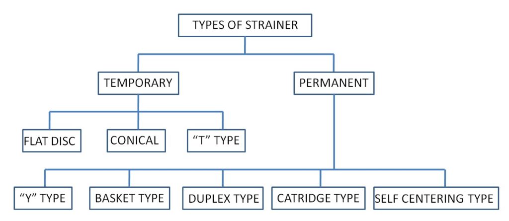
Types of strainers Attachment –I
4.1.1 Temporary Strainers
These are designed for short periods of application for example fitted during start up period of a new system, or when re-starting a system after shut-down and maintenance.These are also used in cases where the characteristics of the process fluid does not permit usage of a permanent strainer.
Temporary strainers are selected based on the type either depicted in the P&ID by Process Licensor or at place such as upstream of pumps where such requirement is not indicated in the P&ID, in order to safeguard the equipment during start up or after a prolonged shutdown.
They are intended to remove coarse debris particles present in the System. After a suitable period in use, they are removed and they can be cleaned and stored for future use.
Strainers of this type are normally designed with standard flange faces so that they can be fitted at a suitable removed the gap can be compensated by either pulling up the flange (for small bore flexible piping) or by inserting a spacer flange and gasket. (Refer attachment – I).
Specifying a particular type of temporary strainer depends also on the configuration of the Piping System.
Temporary strainers are of the following types:
a) Flat Disc Type
These are normally perforated plates.
b) Conical Basket Type
These may be of perforated plate with supported wire mesh. They have higher dirt capacity, normally have a lower pressure drop and provide fine filtering.
c) T-Type Strainer
Where fitting of above strainers is difficult or impartial on a particularly configured Piping System, T-Type Strainer can be used which can be inserted to match a blind on one side T-junction fitting in the pipeline and can be also easily removed. These strainers are of a through shape, referred to as bath tub strainers.
4.1.2 Permanent Strainers
These are of the following types:
a) Y-Type Strainers
These are of Y-Type configuration with a cylindrical strainer element housed in Y-Leg of Strainer. They can be used both in horizontal and vertical (down flow) lines. The element is retained by a plug end which can be opened for cleaning the element. In order to facilitate quick clean out without removing the element a drain connection with a valve is provided as part of “Y” Leg.
These are generally used in pipelines upto 150NB to 200NB in size. The Y-pattern offers lesser resistance to the flow and hence lowers the pressure drop. The limitation of this type of strainer is its limited filtration area, hence it is used on a clean fluid where the necessity of cleaning the strainer is infrequent.
b) Basket Type Strainers
On larger pipelines basket type strainers are preferred. These may be of inline or off line type. The principal advantages of basket strainers is that they can provide greater dirt holding capacity and can have easier access for removal of the strainer for cleaning. They, do however, normally have a higher pressure drop than simple Y-Type Strainers.
These are generally used with liquids wherein regular or frequent cleaning is required.
Basket strainers may be further divided into the following types :
i. Single Sieve
Wherein only one basket doers the filtration, suitable where the dirt load is not very high and high pressure drop is permissible.
ii. Double Sieve
Wherein two baskets work in parallel, suitable for high flow rates and if high pressure drop is not permissible. This is achieved by providing a larger filtration area in comparison to single sieve design.
iii. Multi-Sieve Basket
This design has a number of sieves arranged in telescopic design so that large filtration area can be provided in a small housing.
For highly viscous application the strainers can be steam jacketed so that the hot flow viscosity fluid is easily filtered and a lower pressure drop is registered.
For removal of ferrous particles the basket strainer may have as special requirement magnetic inserts so that the ferrous particles are attracted to the suspend magnetic inserts.
c) Duplex or Dual Type Strainers
These are desired when a continuous operation is required and a shut-down is not possible. The duplex design facilitates cleaning of one element while the other is in operation.
This is generally preferred for highly viscous fluids such as fuel oil where chances of impurities are fairly higher as compared to other fluids.
The basket type strainer covered above can be converted into duplex type by :
i. Interconnecting two strainers covered by 2 numbers of 3-way valves for compact design or
ii. By interconnecting two strainers by 4 nos. 2-way gate valves.
d) Catridge Type Filters
Are produced in a wide variety of configurations and material of construction. Filter media includes yarns, felts, papers, resin, bonded fibres and woven wire cloth.
The filter element (actual catridge) of a catridge filter is normally designed as a disposable component to be replaced with a new one when clogged.
e) Self Clearing Strainers
These may be used as an alternative to duplex types where continuous supply is critical in a process system.
Cleaning may be by using a brush or a scraper to comb out solid particles accumulated around catridge stack which will get deposited in the sump.
Motorised self cleaning strainers can be used when :
a) Constant pressure drop is desired
b) Strainer is inaccessible for manual maintenance
c) The fluid is too viscous
d) The plant is costly and a shut-down is out of the question.
These are being handled by Mechanical Department.
-
Definition of Strainer element and its Basis of Selection
The strainer element is the heart of all types of strainers. Its selection in terms of material of construction, area, mesh size etc is the key to prove its efficiency. Refer table below showing assumption for selection of strainer element.
Sr.No. Type of Strainer Type of Element Mesh/Filtration
Size RangeFiltration Area 1
Flat Disc Perforated Plates Coarse 1/8” Less than pipe cross section area 2
Conical Conical 20 to 200 mesh Refer DPG Standard More than pipe cross section area available 3
“T” Type Half cone shaped 20 to 200 mesh “ 4
“Y” Type Cylindrical 20 to 200 mesh “ 5
Basket Type Cylindrical Upto 2 micron “ 6
Duplex Cylindrical Upto 2 micron “ 7
Catridge Catridge Filtration Upto 0.2 micron “ 8
Self Cleaning Plate type with cleaning blade Filtration Upto 25 micron