A device that moves fluids (liquids or gases), or sometimes slurries, by mechanical action is termed as Pump. Pumps operate by some mechanism (typically reciprocating or rotary), and consume energy to perform mechanical work by moving the fluid. Pumps operate via many energy sources, including manual operation, electricity, engines, or wind power, come in many sizes, from microscopic for use in medical applications to large industrial pumps.
Mechanical pumps serve in a wide range of applications such as pumping water from wells, aquarium filtering, pond filtering and aeration, in the car industry for water-cooling and fuel injection, in the energy industry for pumping oil and natural gas or for operating cooling towers.
2. Types of Pumps
Pumps may be classified on the basis of the applications they serve, the liquids they handle, and their orientation in space.
However all such classifications are limited in scope and tend to substantially overlap each other. A more basic system of classification is principle by which energy is added to the fluid and based on this principle; all pumps are divided into three major categories:
2.1 Kinetic (dynamic): In these pumps, energy is continuously added to increase the fluid velocities within the machine to values greater than those occurring at the discharge, so subsequent velocity reduction within or beyond the pump produces a pressure increase. Refer Figure-1 for classification of Kinetic Pumps.
2.2 Positive Displacement: In these pumps, energy is periodically added by application of force to one or more movable boundaries of any desired number of enclosed, fluid-containing volumes, resulting in a direct increase in pressure up to the value required moving the fluid through valves or ports into the discharge line. Refer Figure-6 for classification of Positive Displacement Pumps.
2.3 Open Screw: Open screw pump is used extensively in waste water plants for moving contaminated water, and in irrigation channels for lifting large volume of water.
Refer subsequent sections for details on these pumps.
2.1 Kinetic (Dynamic) Pumps
Kinetic (Dynamic) pumps may be further subdivided into several varieties of centrifugal and other special-effect pumps. Figure 1 presents in outline form a summary of the significant classifications and sub classifications.
2.1.1 Centrifugal Pumps
The centrifugal pump is the most widely used process pump and accounts for over 95% of all installations. Centrifugal pumps are universally used because they are low in first cost and maintenance, simple to operate, provide a wide range of easily controlled, non-pulsating flow, and are suitable for clean, abrasive, corrosive or non-lubricating fluids. In addition, they are quiet, adaptable to motor, turbine or engine drive, can be obtained in a wide capacity-head range to handle fluids varying in temperature and have low space requirements.
Centrifugal pumps are classified as either radial flow (figure 2) or axial flow (figure 3). In radial flow pump, flow enters the center of the rotating wheel (impeller) and is propelled radially to the outside by centrifugal force. Within the impeller the velocity of the liquid is increased, and this is converted to pressure by the case.
In axial flow pump, flow is parallel to the axis of the shaft. A velocity is imparted by the impeller vanes, which are shaped like airfoils.
Radial flow pumps develop a higher head per stage and operate at slower speeds than axial flow pumps. Therefore, axial flow designs are used in very high flow rate, very low head applications.
Most pumps are neither radial flow nor completely axial flow but have a flow path somewhere in between the two extremes i.e. mixed flow pumps. Its discharge characteristic is, therefore, a mixture of radial and axial flow pumps. It is also used for very large flows like the axial pump and, because its flow path has a radial component, it is capable of generating a higher head than the axial pump.
A centrifugal pump, in its simplest form, consists of an impeller rotating within a casing. The impeller consists of a number of blades, either open or shrouded, mounted on a shaft that projects outside the casing. Its axis of rotation may be either horizontal or vertical, to suit the work to be done. Closed-type, or shrouded, impellers are generally the most efficient. Open- or semi open-type impellers are used for viscous liquids or for liquids containing solid materials and on many small pumps for general service. Impellers may be of the single-suction or the double suction type, single if the liquid enters from one side, double if it enters from both sides.
Multistage Centrifugal Pumps are used for services requiring heads (pressures) higher than can be generated by a single impeller. All impellers are in series, the liquid passing from one impeller to the next and finally to the pump discharge. The total head then is the summation of the heads of the individual impellers. Deep well pumps, high-pressure water-supply pumps, boiler-feed pumps, fire pumps, and charge pumps for refinery processes are examples of multistage pumps required for various services.
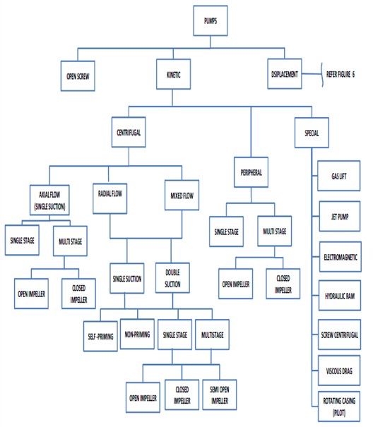
Figure 1: Classification of Kinetic Pumps
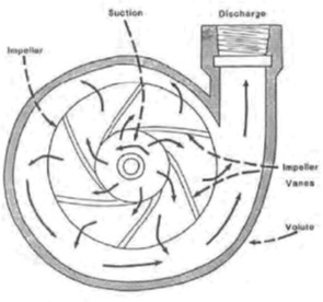
Figure 2: Radial Flow Centrifugal Pump
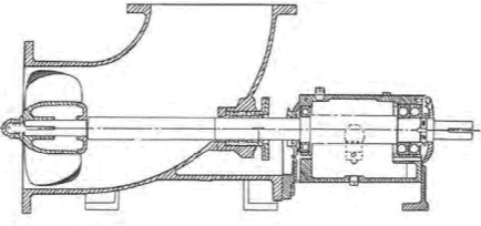
Figure 3: Axial Flow Centrifugal Pump
2.1.2 Peripheral Pumps
Turbine or regenerative or peripheral pumps are somewhat similar in appearance to the common variety of centrifugals, but their internal construction is such that they are capable of developing high discharge heads at low flow rates. Due to the small internal clearance between the impeller and a portion of the casing, the pumped liquids must be free of abrasive particles and should not be corrosive or more viscous.
Applications of turbine pumps require careful evaluation of the maximum pressures which can be developed at zero flow condition. Excessive electrical and pressure overloads are prevented by suitable bypasses and relief valves. Extra consideration is also required in specifying control valve pressure drops due to the characteristic steep Head-Capacity curve.
2.1.3 Special Pumps
a) Gas Lift Pumps
The Gas (air) lift is a device for raising liquid by means of compressed air. In the past it was widely used for pumping wells, but it has been less widely used since the development of efficient centrifugal pumps. It operates by introducing compressed air into the liquid near the bottom of the well. The air-and-liquid mixture, being lighter than liquid alone, rises in the well casing. The advantage of this system of pumping lies in the fact that there are no moving parts in the well. The pumping equipment is an air compressor, which can be located on the surface.
b) Jet Pumps
Jet pumps are a class of liquid-handling device that makes use of the momentum of one fluid to move another. Ejectors and injectors are the two types of jet pumps.
The ejector, also called the siphon, exhauster, or eductor, is designed for use in operations in which the head pumped against is low and is less than the head of the fluid used for pumping.
The injector is a special type of jet pump, operated by steam and used for boiler feed and similar services, in which the fluid being pumped is discharged into a space under the same pressure as that of the steam being used to operate the injector.
In jet pump (figure 4) pumping fluid enters through the nozzle at the left and passes through the venturi nozzle at the center and out of the discharge opening at the right. As it passes into the venturi nozzle, it develops a suction that causes some of the fluid in the suction chamber to be entrained with the stream and delivered through this discharge.
The efficiency of an ejector or jet pump is low, being only a few percent. The head developed by the ejector is also low except in special types. The device has the disadvantage of diluting the fluid pumped by mixing it with the pumping fluid. In steam injectors for boiler feed and similar services in which the heat of the steam is recovered, efficiency is close to 100 percent. The simple ejector or siphon is widely used, in spite of its low efficiency, for transferring liquids from one tank to another, for lifting acids, alkalies, or solid- containing liquids of an abrasive nature, and for emptying sumps.
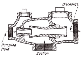
Figure 4: Simple ejector using a liquid-motivating fluid
c) Electromagnetic Pumps
All electromagnetic pumps utilize the motor principle. A conductor in a magnetic field, carrying a current which flows at right angles to the direction of the field, has a force exerted on it, the force being mutually perpendicular to both the field and the current. In all electromagnetic pumps, the fluid is the conductor. This force, suitably directed in the fluid, manifests itself as a pressure if the fluid is suitably contained. The field and current can be produced in a number of different ways and the force utilized variously.
The major classifications of electromagnetic pumps, either conduction or induction, is based on the method employed to cause the electric current to flow in the pumped liquid.
d) Screw Centrifugal Pumps
These pumps have a large diameter screw instead of the more common radial impeller found in centrifugal pumps. Thick sludge and large solids can be moved because of low NPSH requirement resulting from the use of the inducer –like impeller. As the pumped material enters at a low entrances angle, a low shear, low turbulence condition exists, resulting in very gentle handling of the fluid. The gentle handling makes it possible to pump slurries of fruits and vegetables, without undue breakup of the constituents. The pump can also be operated in reverse rotation, which is advantageous for clearing clogged suction lines.
e) Viscous Drag (Disc Pump)
The disc pump system operates solely using the principles of boundary layer and viscous drag, two phenomenon well- known in fluid engineering. Although superficially the disc pump looks like a centrifugal unit, it has no impeller in the traditional sense, and used instead a series of parallel, rotating disc (disc assembly) to generate the energy necessary to move product.
The key difference between the disc assembly and a standard centrifugal pump impeller is that, with the disc assembly, pumpage does not impinge on the rotating pump mechanism, so that it generates a pulsation- free, laminar flow pattern through the pump. The disc pump can operate effectively in hard-to-pump applications because it lacks an “impingement” device, which results in nominal contact between the pump and pumpage.
f) Rotating Casing (Pilot Pumps)
The basic principal for pilot pump (figure 5). is the liquid enters the intake manifold and passes into a rotating case where centrifugal force accelerates it A stationary pick-up tube positioned on the inner edge of case, where pressure and velocity are greatest, coverts the centrifugal energy into a steady, pulsation-free, high-pressure stream. The simplicity of the pump lies in the fact that there is only one rotating part, the seal is exposed only to suction pressure and no seal is required at the high-pressure discharge. The pump, turning at speed from 1325 to 4500 rpm, will generate head roughly four times that of a single-stage centrifugal pump operating at a similar speed. Efficiency is less than for conventional centrifugal pumps. In small sizes, required NPSH may be low as 4 feet, but in large sizes, caution must be used. Required NPSH may be as high as 100 feet.
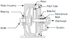
Figure 5: Rotating Casing Pump