Positive displacement pumps are essentially divided into reciprocating and rotary types, depending on the nature of movement of the pressure-producing members.
Each of these major classifications may be further subdivided into several specific types of commercial importance, as indicated in Figure 6.
2.2.1 Reciprocating Pumps
There are two classes of reciprocating pumps: piston pumps or plunger pumps and diaphragm pumps. The action of the liquid-transferring parts of these pumps is the same, a cylindrical piston, plunger, or bucket or a round diaphragm being caused to pass or flex back and forth in a chamber. The device is equipped with valves for the inlet and discharge of the liquid being pumped, and the operation of these valves is related in a definite manner to the motions of the piston.
In all modern design reciprocating pumps, the suction and discharge valves are operated by pressure difference. That is, when the pump is on its suction stroke and the pump cavity is increasing in volume, the pressure is lowered within the pump cavity,permitting the higher suction pressure to open the suction valve and allowing liquid to flow into the pump. At the same time, the higher discharge-line pressure holds the discharge valve closed. Likewise on the discharge stroke, as the pump cavity is decreasing in volume, the higher pressure developed in the pump cavity holds the suction valve closed and opens the discharge valve to expel liquid from the pump into the discharge line. The overall efficiency of these pumps varies from about 50 percent for the small pumps to about 90 percent or more for the larger sizes.
If liquid is pumped during linear movement in one direction only then the pump is classified “single acting.” If the liquid is pumped during movement in both directions it is classified as “double acting.”
Reciprocating pumps may be of single-cylinder or multi-cylinder design. Multi-cylinderpumps have all cylinders in parallel for increased capacity.
a) Piston / Plunger Pumps
Piston or Plunger Pumps are reciprocating pumps that use a plunger or pistonto move media through a cylindrical chamber. The plunger or piston isactuated by a steam powered, pneumatic, hydraulic, or electric drive.
Piston pumps and plunger pumps use a cylindrical mechanism to create areciprocating motion along an axis, which then builds pressure in a cylinder orworking barrel to force gas or fluid through the pump.
Piston-type pumps may be single-acting or double acting; i.e., pumping maybe accomplished from one or both ends of the piston. Plunger pumps arealways single-acting. There are two ordinary types of piston pumps, simplexdouble-acting pumps and duplex double-acting pumps.
Plunger pumps differ from piston pumps in that they have one or moreconstant-diameter plungers reciprocating through packing glands anddisplacing liquid from cylinders in which there is considerable radialclearance. They are always single- acting; in the sense that only one end ofthe plunger is used in pumping the liquid. Plunger pumps are available withone, two, three, four, five, or even more cylinders.
Simplex plunger pumps mounted singly or in gangs with a common drive arequite commonly used as metering or proportioning pumps .Frequently avariable-speed drive or a stroke adjusting mechanism is provided to vary theflow as desired. These pumps are designed to measure or control the flow ofliquid.
The advantages of reciprocating pumps are:
- The efficiency is high regardless of changes in required head. Efficiencies ofthe order of 85% to 95% are common.
- The efficiency remains high regardless of pump speed, although it tends todecrease slightly with increasing speed.
- Reciprocating pumps run at much lower operating speeds than centrifugalpumps and thus are better suited for handling viscous fluids.
- For a given speed the flow rate is constant regardless of head. The pump islimited only by the power of the prime mover and the strength of the pumpparts.
Because of the nature of their construction, reciprocating pumps have the following disadvantages when compared to centrifugal pumps:
- They have higher maintenance cost and lower availability because of thepulsating flow and large number of moving parts.
- They are poorer at handling liquids containing solids that tend to erodevalves and seats.
- Because of the pulsating flow and pressure drop through the valves theyrequire larger suction pressures (net positive suction head) at the suctionflange to avoid cavitation.
- They are heavier in weight and require more space.
- Pulsating flow requires special attention to suction and discharge pipingdesign to avoid both acoustical and mechanical vibrations.
Dampeners for Reciprocating Pumps
In reciprocating pumps, the oscillating motion of the plungers creates disturbances(pulsations) that travel at the speed of sound from the pump cylinder to the pipingsystem. These pulsations cause the pressure level of the system to fluctuate withrespect to time. In order to lessen potentially damaging pulsations in piping fromthis pressure fluctuation, pulsation dampeners may be installed in the suctionand/or discharge piping of the reciprocating pump. There are basically four typesof pulsation dampeners’ (i.e. liquid- filled, gas-liquid interface, gas-cushioned, andtuned acoustical filter).
Liquid-filled dampeners (Figure 7) are large surge vessels located close to thepump. The volume of the vessel is normally ten times the pump throughput perminute. Liquid-filled dampeners are maintenance free and incur no pressure drop.They are heavy when filled with liquid, however, and they tend to require a lot ofspace.
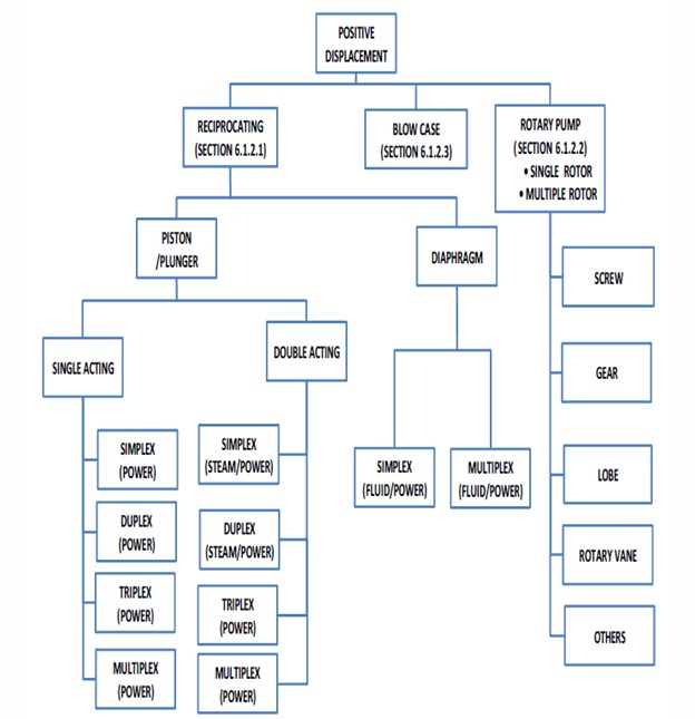
Figure 6: Classification of Positive Displacement Pumps
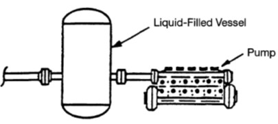
Figure 7: Liquid-Filled Dampener
A gas-liquid interface pulsation dampener (figure 8) consists of a vessel that ispartially filled with liquid and partially filled with gas. This pulsation dampener is effective because the high compressibility of the gas absorbs the pressure pulses.Due to the compressibility of the gas, these dampeners are much smaller thanliquid-filled dampeners. However, since the gas could be dissolved slowly in theliquid that is being pumped, the gas-liquid interface must be monitored. Inaddition, these dampeners are impractical at locations where pressures varywidely.
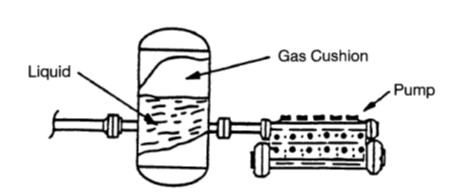
Figure 8: Liquid-Filled Dampener
Gas-cushioned pulsation dampeners (Figure 9) use a pressure bladder to keep gasfrom being absorbed in the liquid. These dampeners are generally small andinexpensive, but they cannot be used in applications where temperatures areabove 300°F. In addition, like gas-liquid interface dampeners, these dampeners areimpractical at locations where pressures vary greatly.
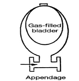
Figure 9: Gas – Cushioned Pulsation Dampener
Dampeners-Tuned acoustical filters (figures 10 and 11) are generally of two types:
Type I and Type II. In Type I, two liquid-filled dampeners are connected by a short section of small-diameter pipe called a choke tube. In Type II, choke tube is installed between the one liquid-filled dampener and the piping system. Both dampening systems are best designed through the use of digital or analog simulation. Tuned acoustical filters can suppress pulsations at all frequencies. In addition, they incur low maintenance costs, and their performance is not affected by temperature. Still, these filters require ample space and are relatively expensive. They also require a pressure drop across the choke tube, there by limiting applicability in low-NPSH situations.
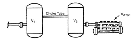
Figure 10 Type I (Dampener -Tuned Acoustical Filters)
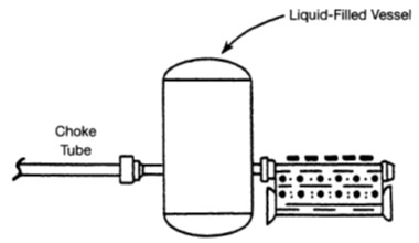
Figure 11 Type II (Dampener -Tuned Acoustical Filters)
b) Diaphragm Pumps
Diaphragm pumps are a special type of reciprocating pump that utilizes the action of a diaphragm moving back and forth within a fixed chamber. Sometimes the diaphragm is used to power a reciprocating pump with air or natural gas.
The advantages of a diaphragm pump are that it can handle large amounts of suspended solids, is inexpensive to repair, can handle low flow rates inexpensively, and can run periodically without any liquid. However, diaphragm pumps require frequent maintenance because they are reciprocating pumps and because the diaphragm has a tendency to fatigue with time. They generally cannot handle very high flow rates, or discharge pressures.
A more common type of diaphragm pump is the air-operated double diaphragm pump which uses pressurized air to actuate the diaphragms instead of a mechanical device.
2.2.2 Rotary Pumps
Rotating positive displacement pumps have rotating parts which form the moving cavity for carrying the fluid from one side and discharging it at the supply side.Rotary positive displacement pumps are of mainly two types based on the number of rotors.
- Single Rotor
- Multiple Rotor
Each of these two types of Rotary Positive Displacement Pump has pumps available with different design features. Screw Pumps and Gear Pumps are most common Rotary Positive Displacement Pumps.
They are useful in high viscosity services such as asphalt, heavy lube oils, crude oiland even greases. When required, steam jacketed casings are available.
a) Screw Pumps
Screw pumps are a special type of rotary positive displacement pump inwhich the flow through the pumping elements is truly axial. The liquid iscarried between screw threads on one or more rotors and is displaced axiallyas the screws rotate and mesh (figure 12). In all other rotary pumps, the liquid is forced to travel circumferentially, thus giving the screw pump with
its unique axial flow pattern and low internal velocities a number of advantages in many applications where liquid agitation or churning is objectionable.
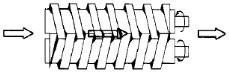
Figure 12: Screw Pump
Progressive Cavity Pump has been referred to as a single-end, single rotor type of screw pump where the pumping elements comprise a single rotor and a stator (figure 13). The stator usually has a double helical internal thread with a pitchtwice that of the single helical stator. This results in two leads on the stator, andone on the rotor. As the rotor rotates inside the stator, two cavities form at thesuction end of the stator, with one cavity closing as the other opens. The cavitiesprogress from one end of the stator to the other. The result is a flow withrelatively little pulsation. Since the longest path through the elements is a spiral,and not far from a straight line, the shear rates will also be low in comparison tothose in other types of pumps.
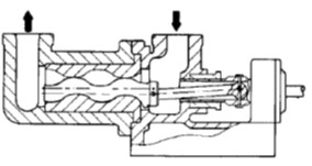
Figure 13: Single Screw Pump- Progressive Cavity Pump
Multiple-screw pumps are available in a variety of configurations and designs(figure 14). All employ one driven rotor in a mesh and one or more sealing rotors.
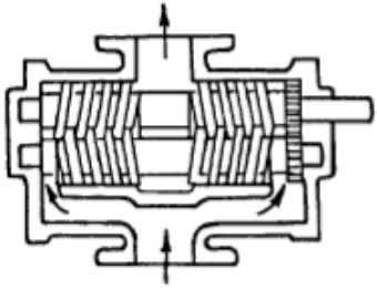
Figure 14: Two Screw Pump
b) Gear Pumps
Gear pumps belong to a positive displacement rotary group, and are made byenclosing two or more gears in a close-fitting housing. A driver turns a shaftconnected to one of the gears, causing it to rotate. This gear drives the othergear through the meshing of the teeth of the two gears, just as with powertransmission gears. As the gears rotate, on one side, the teeth are comingout of mesh with each other (Figure 15 &16). As a tooth is pulled out of thespace between two teeth of the other gear, it creates a vacuum. Since thehousing forms a seal all around the set of gears, the liquid that rushes intothis space to fill this void has to come in through the pump’s suction port.Once the spaces between gear teeth are filled with liquid, the liquid rides inthese pockets, trapped in place by the housing, until it reaches the dischargeside of the pump. The liquid stays in place between the teeth until it reachesthe other side of the gear mesh, where the teeth are coming together. Then,when a tooth from the other gear comes into the space between the teeth,the liquid there is forced out. Since the housing still forms a seal around thegears, the only place for the displaced liquid to go is out the pump’sdischarge port. The pump thus operates like a conveyor belt, with thepockets of liquid between the gear teeth being picked up at the gear mesh,carried to the other side, and dropped off at the other side of the mesh.
There are two basic types of gear pumps (i.e. external and internal). Externalgear pumps usually have two gears with an equal number of teeth on theoutside of each gear. Internal gear pumps have one larger gear with the teethturned inward, meshing with a smaller gear with external teeth. If the largergear has one tooth more than the inner gear, the two gears form a seal bythemselves. If the larger gear has at least two teeth more than the smallergear, then a crescent-shaped projection of the housing go between the twogears to help form a seal. The operating principle is the same for all of thesetypes of pumps, and they operate in similar fashion.
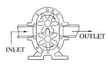
Figure 15: External Gear
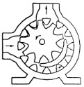
Figure 16: Internal Gear
c) Lobe Pumps
A lobe pump differs from other gear pumps because it uses lobed elements instead of gears (figure 17). The element drive also differs in a lobe pump. Ina gear pump, one gear drives the other. In a lobe pump, both elements are driven through suitable external gearing. Lobe pumps can be either single- or multiple-lobe pumps and carry fluid between their rotor lobes much in the same way a gear pump does. They are commonly used to pump sludge in waste water treatment plants and in stainless steel systems for handling foodstuffs in the food, beverage, dairy, and pharmaceutical industries.
d) Rotary Vane Pumps
Two basic types of Rotary vane pumps exist. The most common is the Rigid sliding metal vane type, and the other is the Flexible or elastomeric vane used for dirty or chemically aggressive fluids.
In Rigid sliding vane pump (figure 18) the rotor is eccentrically located in the pump casing and vanes slides in and out to maintain contact with casing wall.
In a Flexible vane pump (figure 19) the rotor is mounted eccentrically in the pump casing and vanes flex to maintain contact with casing wall. The pumping action is created by variation in volume between the vanes.
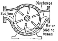
Figure 18: Typical Sliding Vane Pump
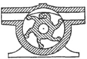
Figure 19: Flexible Vane Pump
2.2.3 Blow Case Pumps
This is a special configuration of a positive displacement pump (figure 20). It consists of two pressure chamber that are alternatively filled with liquid. When a chamber is filled, air or steam is forced into the chamber. These cause the contents to be discharge into the system. The two chambers alternate in this section, resulting in a fairly constant discharge. It is popular for pumping hotcondensate because there is no heat loss and flashing liquid can be transferred.
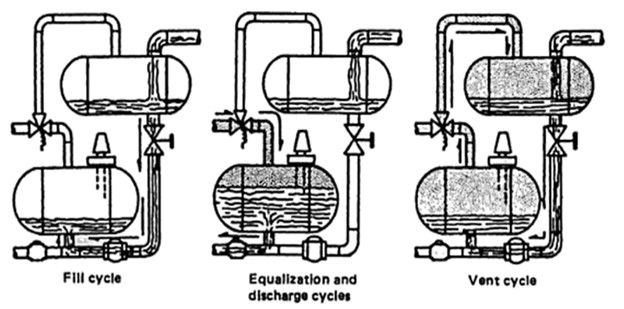
Figure 20: Blow Case Pump Operation
2.3 Open Screw (Archimedes) Pump
An open-screw pump (figure 21) consists of a U-shaped channel into which arotating screw fits tightly (minimal clearances). The channel angled at inclinationof up to 450, takes liquid from a lower level and literally “screws” the water fromthe lower to higher level. The open- screw pump does not develop any pressure asit is merely a conveyor. This pump is used extensively in waste water plants formoving contaminated water, and in irrigation channels for lifting large volume ofwater.
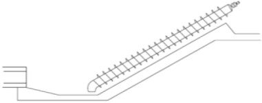
Figure 21: Open Screw Pump