-
PLASTIC PIPING SYSTEM:
The Plastic Piping System consists of Piping Profile fabricated from plain end pipe, plain and flanged end Fittings (i.e. Elbows and Reducers) and stub-in branch connections. The Flanged Joints are Stub Ends with loose Backing Flanges. In case of Flanged Tapping Long Stub Flanges are recommended to be used in place of pipe stub-in and Short Stub Flanges.
The pipe to pipe and pipe to fittings joints are laminated joints. Accessories to Piping System include Soft Rubber/ CAF Gaskets and Full Threaded Fasteners with Washers.
-
Design Considerations for Plastic Piping:
- Owing to weak mechanical properties a minimum of NS 2” line size is recommended for Plastic Piping. However tapping of small size (i.e. smaller than NS 2”) are permitted for drain/ vent etc. provided the branch connection is adequately supported.
- Since the piping joints employed as per most Standard are laminated joints (Refer DIN 16966 Part 8 for details) requiring a large overlap length, care shall be taken to ensure adequate spacing between the joints to avoid the overlapping of the laminate structure.
- Owing to its large Co-efficient of Thermal Expansion the Plastic Pipelines exhibit a high tendency to grow under moderate temperatures. This may result into sizable deflection of the branches and the corners of the Piping Profile. It shall therefore be ensured that the branch connections are not over stressed, either by providing adequate flexibility on the branch piping or by fixing the branch points by external means to disallow its deflection.
If free movement of the corners of the piping profile can be allowed (i.e. e.g. not being hindered by any other external item) then it is preferable to leave the profile to grow freely.However if the growth of the profile has any adverse effect on the system stability (i.e. e.g. supports falling off from the external structure) it may be appropriate to restrict the growth of the sides of the profile by providing fixed supports at various locations as per Plastic Piping Support recommendations.
- Unlike Steel, bellows are not used on Plastic Piping. The thermal stress behavior is addressed either by providing in-built flexibility in the system or by arresting the axial growth of the pipe runs within the pipe length itself. In case the later method is employed, the pipe may have to be guided at close intervals to avoid failure due to buckling.
- Owing to its weak nature, the plastic piping shall not be supported by a line contact between the pipe surface and the external structure taking the load. Hence as a general rule Clamp and Shoe type supports shall be employed on Plastic Piping System
- All concentrated loads (e.g. On-line Valves, Instruments etc) shall be directly supported to ensure that the load is transferred to the grade/ external structure without stressing the piping.
- All the valves employed on Plastic Piping shall be provided a Fixed Type Support to ensure that the Piping is not over stressed in case of jamming of the Valve hand wheel while operating.
- Due to excess thickness of Plastic Pipe (as compared to Steel) it is likely to obstruct the opening of the flap of Sandwich type Butterfly/ Wafer Check Valve into the pipe. In order to address the above issue the Spacer Rings (made of same or equivalent material as pipe) will be employed across the valve. The above Spacer Ring is procured as a Special Part.
-
Bill of Material Considerations for Plastic Piping:
The Bill of Material for Plastic Piping is worked out similar to the steel piping with the following exceptions.
- Since most Standard requires the Flanged (one end or both end flanged) Fittings i.e. Elbows and Reducers to be shop fabricated it requires a careful consideration to assess the precise requirement of the Flanged Fitting of each type and differentiate the same from the plain end fittings.
- Since all Branch connections are stub-in type the material required for fabricating branch connections shall be accounted for, while computing the pipe quantities.
- In case of Flanged Tapping the branch connection is made by employing Long Stubs Flange instead of pipe stub-in with a Short Stub Flange. Care shall therefore be exercised to differentiate the above Flanges Tapping from the rest of branches to be able to estimate the requirement of Long and Short Stub Flanges accurately.
- Spacers shall be accounted for (as Special Parts) across all Sandwich Type Butterfly Valves and Wafer Check Valves.
-
Technical Specification Considerations for Plastic Piping:
- The Vendors scope includes supply, fabrication, erection, supporting and testing of Plastic Piping as per the Enquiry Document.
- Items such as Gaskets, Fasteners, On-line Valves, Instruments, Special Parts are excluded from the Vendor’s scope.
- All Piping items in Vendors scope shall be fabricated by Hand Lay-up method to ensure superior Chemical Resistance properties.
- The whole Laminate Structure shall be UV absorbent.
- The Piping items shall be fabricated and supplied as per the UN 3030 –16 (Part-1) and all other relevant DIN Standards referenced there in.
- The Stub Ends for Flanges shall be fabricated as monolithic structure
- The Flanged Elbows shall be in accordance with DIN 16966 Part-2 without the straight portion.
- The Piping Material shall comply with the General Quality and Testing Requirements as per DIN 16966 Part 1
- The Inspection and Testing Shall include, but not limited to, the following test
Short Term Hydro test
Laminate Structure and Glass Content
Adhesive Shear Strength
Hardness Test (Styrene Content)
Surface Finish and Dimensional Check - FRP Piping with Thermoplastic (e.g. PVC, PP etc) liner shall be subject to additional leak test using air at 0.5 Bar-g (max) prior to lamination of liner weld seams.
- It is recommended to follow the Laminate Structure of the FRP Piping as per most Technical Specification. The Vendor shall confirm the same for the specified wall thickness indicated in the Enquiry Document. Alternatively the Vendor can propose its own Laminate Structure for company’s review and approval.
-
Installation Consideration for Plastic Piping:
- The Plastic Piping System shall be installed with permanent supports in place. Erection of Plastic Piping with temporary supports is not acceptable.
- The pipes shall not be stretched in order to match the terminal ends
- The Flange Joints shall be tightened to the specified Torque Value only by employing Torque Wrench.
- As far as possible the Piping profile shall be prefabricated in the Vendors shop at site, leaving only a few field joints for final fit-up.
- In case of FRP Piping with Thermoplastic Liner, the Field Weld will always be located at the convenient height/ location to allow down hand welding/ jointing.
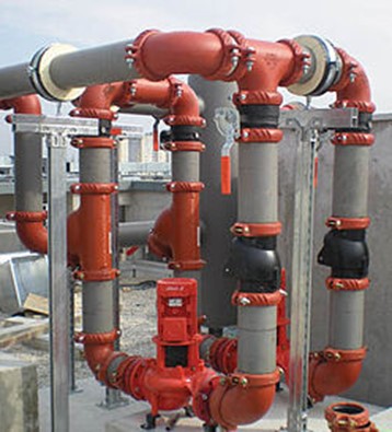
Fig 1.Composite Piping System