1. Introduction
Fluid pressure is defined as the measure of force per-unit-area exerted by a fluid, acting perpendicularly to any surface it contacts. Pressures and pressure measurements can be extremely complex and complicated. However, if the proper techniques are used, it is possible to obtain accurate pressure measurements.
Selection of pressure instrument for a particular application must be done carefully, taking into consideration various aspects such as process conditions including the metallurgy requirements, turndown requirements, accuracy, installation requirements etc.
While selecting a pressure instrument for a particular application, the process data such as fluid phase, pressure, temperature, density and viscosity must be correctly defined for all operating conditions including start-up, emergency operations and design conditions.
One typical case is that of a Compressor which has tripped without de-pressurization.
Under such condition the Compressor suction pressure will be higher than the normal operating suction pressure and the transmitter should be calibrated to suit this pressure value. Such pressure is called “settled out pressure”.
Another important parameter for selection is the turndown requirements, based on which we can select the pressure instrument to suit the maximum and minimum conditions within its specified accuracy limits.
In addition to the above, the installation requirements of the selected pressure instrument shall be carefully addressed taking in to account visibility, accessibility, because these requirements may affect the piping layouts.
2. Categorization of Pressure Instruments
The most commonly used pressure measuring devices in industry are pressure gauges and pressure transmitters.
Gauges i.e. Local Instrument
Gauges can be further classified in two categories
a) Pressure Gauge
b) Differential Pressure Gauge
Transmitters
Transmitters can be further classified in two categories
a) Pressure Transmitter
b) Differential Pressure Transmitter (DPT). DPTs are used for Differential Pressure measurement, Level measurement, Flow measurement.
2.2 Material Selection
All wetted parts of transmitters, pressures gauges, etc. including ancillary equipment shall be AISI 316L type stainless steel as a minimum and other materials are required for the specified fluid/process conditions.
With rule of thumb, the selection of wetted parts to be identical to that of Valve trim mentioned in respective Piping material specification as a minimum. Material compatibility must be considered in more detail for the Sensor & wetted parts of a pressure measuring instrument as compared to pressure-containing pipe and valve, the reason being the sensor is a diaphragm of few “mm” thickness.
The pressure-containing parts of the instruments shall be compatible with the design / operating conditions.
Where applicable, all instrument material and components in sour process applications shall be certified per NACE MR 01-75 (latest edition) / ISO 15156.
Special attention shall be paid to corrosion from the surrounding atmosphere for instruments and ancillary equipment. The numerous environments in which the meter can be used make it difficult to define process fluid compatibility for every possible material combination. The difference in chemical composition of most environments can be characterized by four variables. These are halogen (E.g.: Chlorine), concentration, pH, chemical potential, and temperature.
Special service applications such as Oxygen service needs specific cleaning requirements / instruction due to the high oxidizing nature and the same shall be carefully considered.
Hydrogen service needs special attention due to the high penetration property (due to small atomic/molecular sizes). The sensor diaphragm material or the diaphragm seal material shall be with Gold plating.
When flanged diaphragm seal pressure instruments are used, it is important to verify the
P-T rating (Pressure – Temperature) where diaphragm flange material is AISI 316 SS and the process connecting flange is of carbon steel.
2.3 Gauges
2.3.1 Pressure Gauge
Pressure gauges used are generally of bourdon tube type with safety pattern design in accordance with EN 837-1. In Oil & Gas sector, usually wetted parts material of construction used is stainless steel 316L as a minimum, with 100 mm diameter white dial with black mark and black pointer. Smaller sizes may be accepted on instruments to be used for pneumatic supply. (In some cases dial size may be 150 mm based on project specifications). For high pressure applications, gauges shall have a solid front design, blow-out rear and seals where application requires them. Definition of High pressure may vary project to project and this needs to verify prior to specifying this particular requirement. Unless specified otherwise pressure gauges shall have ½ inch NPT(M) bottom-connection and shall be direct mount type. Type of thread shall be stamped on shank. They shall be isolated from process using Double Block and Bleed valve (DBB) or Single Block and bleed valve (SBB). Process isolation is dependent on Project Isolation philosophy. Further at pressure gauge end, mono-block assembly may be used if called upon in project instrumentation philosophy. Gauges shall be provided with an external zero adjustment mechanism. Casing material shall be either phenolic or AISI 316 stainless steel minimum, glass shall be shatterproof safety glass, retained by screwed or bayonet type bezel ring complete with a suitable gasket. Gauges shall be rated IP 65 or IP 54 as a minimum (Ingress Protection rating may change project to project).
Where excessive vibration is probable, liquid filled dampening devices shall be used.
Snubbers shall be provided for pulsating/oscillating services. Over range protectors shall be provided where the design pressure of vessel/system exceeds the maximum over range pressure. Typical example of excessive vibration is pressure gauge installed at pump discharge.
Pressure gauge ranges shall be selected such that normal working pressure is “between 50 to 75” percent of the scale.
Based on standard ranges available with reputed suppliers, following ranges are generally specified. However this is not the limitation. ASME B40.100 recommends that normal operating pressure be confined to 25%-75% of the scale. If pulsation is present in the process, maximum operating gauge pressure should not exceed 50% of the full-scale range.
- · For pressures above atmospheric pressure.
0/0,6; 1; 1,6; 2,5; 4; 6; 10; 16; 20; 25; 40; 60; 100; 160; 200; 250; 300; 400; 600 and 1000 Bar-g.
- · For vacuum gauges:
-1/0 Bar-g
- · For combined pressure/vacuum gauges
-1/0/0,6; -1/0/1,5; -1/0/3; -1/0/9 Bar-g.
Gauges shall have accuracy equal to 1% of span, including hysteresis, linearity and repeatability. This accuracy is to be maintained after momentary overpressure and cycling up to 1.25 times the maximum full-scale pressure.
Where bourdon tube type gauges are not suitable due to corrosion, plugging, etc then pressure gauges with diaphragm seals are used.
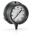 Typical Pressure Gauge with Solid Front |
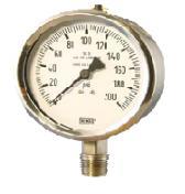 Typical Pressure Gauge |
2.3.2 Pressure Gauge Accessories
Pressure gauge accessories are as follows:
(i) Diaphragm Seal
Pressure gauges/ Transmitters with diaphragm seals are used are used in applications where bourdon tube type gauges are not suitable due to corrosive, viscous, waxy, sticky, plugging etc. services . Also in case if the fluid temperature under any normal or abnormal operating condition exceeds the maximum allowable temperature of the sensing element
Diaphragm Seal shall normally be integral with the instrument. The application of diaphragm seals with capillary extensions shall be kept to an absolute minimum. The complete diaphragm seal assembly shall be of welded construction. Screwed connections shall not be used. For transmitters, the capillary tubing shall be welded directly onto both ends of the sensor. Diaphragm seals shall be ordered as an integral part of the instrument.
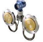 Diaphragm seal with capillary |
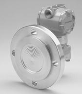 Flush flange mounted PT |
|
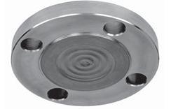 Typical flush flange Diaphragm |
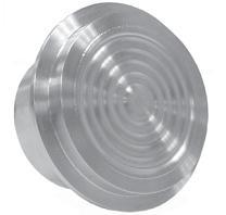 Diaphragm Seal without back-up flange |
|
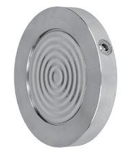 Wafer type Diaphragm Seal |
Special attention shall be paid to diaphragm seals on low differential pressure and pressure applications. For low pressure measurement good practice is to increase the size of sensing element so that minor changes are captured. Usually for low pressure measurement with diaphragm seal, the size of diaphragm shall be 3” minimum.
When a diaphragm seal is required, the largest practical diaphragm size and minimum capillary size should be applied. Typically diaphragm of minimum 2” should be used however minimum allowable size to be followed as per Project specifications. Diaphragm seals shall be ordered as an integral part of the instrument.
The capillary tubing material shall be of AISI 316SS and be shielded by flexible stainless steel tubing with a neoprene or PVC cover, according to manufacturer’s standard.
The length of the capillary tubing shall suit the application but shall be at least 1 meter.
For differential pressure applications with two remote seals, the two parts of the capillary tubing shall be of the same length to nullify the inaccuracy caused by varying ambient conditions.
If capillary tubing is exposed to direct sun radiation or to extreme temperature fluctuations (e.g. arctic environments), thermal insulation and, if required, tracing of the capillary tubing should be considered, to reduce measurement errors as a result of varying ambient temperatures and exposure to solar radiation.
Filling liquids shall be selected in consultation with the party responsible for the process design and with the Manufacturer. The seal filling liquid shall be suitable for the upper and lower pressure and temperature limits of the process / design / ambient and shall not impact the process in case of rupture of the diaphragm. Filling fluids for capsules and diaphragm seals shall not present a hazard to the environment in the event of a diaphragm failure.
Special attention shall be paid to diaphragm seals used in vacuum service, i.e. services with a sub-atmospheric lower design pressure. Filling liquids and connections shall be suitable for vacuum service as well special attention shall be paid to the use of diaphragm seals handling small ranges (typically 50 mbar or smaller) and interface level measurement.
Facilities shall be provided to test and calibrate the diaphragm seal type transmitters under operating conditions.
In case of wafer type or diaphragm seal with back-up flange, back-up flange is a non wetted part, possibility must be checked to use back-up flange with material of construction of Carbon steel. This arrangement is a cost effective solution and acceptable in industry. However Pressure – Temperature rating check shall be done thoroughly prior to completion of Technical evaluation
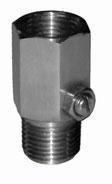
(ii) Gauge Saver
Gauge saver also known as over pressure protector and use to protect the pressure gauge from over pressure. The gauge saver has a predefined set-point at which it will not allow any media to flow. The set-point typically can be varied for a max span of 10% of set pressure.
Gauge Saver
(iii) Snubber (Pulsation Damper)
Snubber (Pulsation Dampers) are used with pressure gauges where sudden pressure shocks and fluctuations are present which cause the pointer to fluctuate rapidly hence making it difficult to take the gauge reading. Snubbers reduce pulsations considerably and hence make the gauge reading easier and also improve the life of the gauge.
Snubber
(iv) Syphon
Syphon is used for steam or high temperature application. Syphon forms barrier of water / liquid in the coil, preventing high temperature attack on pressure sensor and the bourdon solder joints.
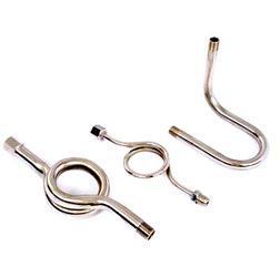
Syphon
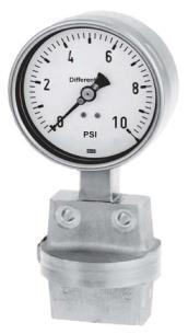
2.3.3 Differential Pressure Gauges
Most of the requirements are identical to that of pressure gauge for Differential Pressure
Gauge also. However based on application, additional features are as described.
Differential pressure gauges shall be equipped with diaphragm or bellows elements, unless otherwise specified on the project data sheet.
Gauges shall be capable of withstanding over-range pressure on either side of the diaphragm, without damage or calibration shift. Similar to pressure gauges the Differential Pressure gauges shall also be specified with solid front design if the line pressure is high even though the differential range may be small.
Manifold is required for Differential Pressure gauge. However based on its design, the manifold may be required of external mounting type.
 Transmitters |
2.4 Transmitters
Generally, pressure transmitters shall be electronic SMART type with HART protocol communication and / or FF protocol if project specification calls for.
The use of pneumatic transmitters for local loops shall be minimized. Where pneumatic transmitters are to be used due to any specific project requirement, the engineer is expected to bring this to the notice of lead engineer / technical specialist.
The pressure / differential pressure transmitter’s elements and body shall be made up of AISI 316 L SS as minimum, unless process conditions dictate otherwise.
The normal pressure shall be read at no greater than 75% of the calibrated span for transmitters reading steady pressure. For fluctuating services the normal pressure shall be read at 60% of the calibrated span.
Differential pressure transmitters, to be used on flow measurement, shall be configurable for square root or linear output.
For low-pressure ranges between -1 barg, and +2 barg, differential pressure instruments shall be used for pressure measurement applications. The low-pressure connection shall be open to atmosphere or connected to a reference zero (Typically inverted siphon can be connected to avoid dust / water ingress).
The electrical signal transmission shall normally be 2-wire system, 4 to 20 mA, 24 V DC. If project demands, the transmitters with Foundation Field bus (FF) protocol should be used for Control & monitoring purpose (connected to DCS system). When FF transmitters are selected, following capabilities should be addressed suitably:
(i) Function Blocks
(ii) Link Active Scheduler (LAS)
(iii) Advance Control function Block
(iv) Compensated mass flow block
(v) Advance diagnostics
Highway Addressable Remote Transducer (HART) protocol should be used for ESD system.
Transmitters connected to ESD system shall be selected with minimum SIL2 certification.
The pneumatic signal transmission range shall be 0.2 to 1 Barg.
Where process pulsation exist a transmitter with inherent damping and adjustable damper shall be used. Transmitters shall have an overall accuracy, including repeatability, equal of 0.25 % of calibrated span, as minimum.
Transmitter body rating shall be 100 barg as minimum.
Differential pressure transmitters shall be capable of withstanding over-range pressure on either side of the sensor element at least equal to the body rating without damage or calibration shift. For example: calibrated range 0 to 10,000 mbar, Body rating 100 barg,
Line pressure (max) 60 barg.
Process connection shall be ½” NPT female & Vent and drain connection shall be ¼” NPT female.
Enclosure shall be rated IP 66 as minimum with M20 x 1.5 mm cable entry. Enclosure material shall be stainless steel for harsh environments. As an alternative, aluminum with epoxy painting, suitable for offshore marine environment, may be considered after obtaining formal approval from Client for the same.
 |
 |
In general, All electronic transmitters shall have an integral indicator (unless otherwise specified). These shall be of the Liquid Crystal Display (LCD) type and shall be configurable to read in percentage or engineering units.
The integral indicators shall be suitable for the location and hazardous area classification.
The construction of the indicator shall ensure instrument continuity in the event of indicator failure.
Special attention shall be given to transmitters installed in ambient conditions where temperature is less than -20 deg. C. Heated enclosures or heated insulating jackets need to be provided to prevent the freezing of local LCD indicator below -20 deg. C.
2.4.1 Transmitter Accessories
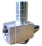
(vi) Two Valve Manifold
For Pressure transmitters, Two Valve Manifolds are used. Usually, these manifolds are mounted directly on Pressure transmitter (Integral mounting). Material of construction of manifolds shall be AISI 316SS as a minimum or superior based on application. Packing Material to be selected based on process temperature limits.
 Two Valve Manifold |
 |
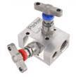
(vii) Three Valve Manifold
For Differential Pressure transmitters, three valve manifolds are used. Usually, these manifolds are mounted directly on D.P.T. (Integral mounting). However whenever three valve manifolds are used, it is important to notify the Hook-up team so that external Drain / Vents can be considered in bulk MTO.
For Differential Pressure Gauge, integral type of manifold should not be considered.
Externally mounted manifold should be used.
Packing Material to be selected based on process temperature limits.
 |
 |
(viii) Five Valve Manifold
For Differential Pressure transmitters, five valve manifolds are used. Usually, these manifolds are mounted directly on D.P.T. (Integral mounting).
|
Transmitters |
|

(ix) Drip Rings
Drip Rings are called as Flushing Rings. These rings are required only when Diaphragm seals are used. In-Situ calibration is also possible if drip rings are used.
Drip ring size and rating shall be suitable for selected diaphragm seal. It shall consist of 2no’s of connections for vent and drain. Typical connection size is ½” however other end connection could be either threaded or flange depending on project requirements.
Material of construction of drip rings shall be identical to that of vessel trim or as indicated in Piping Material Specification.
As a good engineering practice, it is advisable to obtain confirmation on material of construction selection from metallurgy expert.
Illustrations are typical and requirements may vary project to project.

very interesting and easy languages. Best for beginners.
Thanks..