1. Need for Spring Hangers
2. Types of Spring Hangers
3. Selection Procedure of Variable Effort Springs
4. Selection procedure of Constant effort springs
5. Spring Selection procedure in Caesar II
1. Need for Spring Hangers:
Generally the use of spring hangers shall be the last resort for a Stress Engineer. However, in some cases depending on the pipe routing and high temperature the use of spring hangers becomes unavoidable.
Some such examples are piping connected to Pump, Compressors, Reboilers, Tanks, etc.
Whenever some rigid supports are not taking load due to its thermal movement or rigid supports are causing overloading effect to equipment connection Piping engineers suggest the use of a spring hanger to share some of the loads and to keep the piping system safe. Selection of the appropriate type of hanger support for any given application is governed by the individual piping configuration and job requirements.
2. Types of Spring Hangers
There are two types of Spring Hangers:
- Variable Effort Spring Hangers: Load varies throughout its operating range
- Constant Effort Spring Hangers: Load remains constant throughout its operating range.
3. Selection Procedure of Variable Effort Springs:
- Identify the support close to the equipment nozzle that may be lifting up during the operating conditions and hence causing nozzle overload.
- Remove the rigid support and add a spring hanger in that location.
- Modify the load cases to include the spring effect and run the analysis. Spring shall be designed at Operating Temperature
- Determine the hot load or operating load required and the pipe movement (up or down) at that support location.
- Choose the spring catalogue of any vendor from the project Approved Vendor List e.g. Anvil, Lisega, PTP, Carpenter & Patterson are some of the popular names.
- Estimate the travel range from the catalogue.
- Select the smallest spring size which has the hot load within the working travel (midrange).
- Note the Spring Rate or Spring Stiffness of the selected Spring Hanger.
- Calculate the cold load as follows:Cold Load = Hot Load + Movement x Spring Rate (For pipe movement up)Cold Load = Hot Load – Movement x Spring Rate (For pipe movement down)
- This calculated cold load shall be within the working range of the selected spring.
- In case the calculated Cold load is not within the working range, then select higher spring size or the next travel range.
- Then calculate the Spring Variability of the selected spring for the system Hot Load and Cold Load.
- As a general practice, the load variability shall be up to 25% throughout the total travel. However, for critical systems such as piping connected to pumps, compressors, reboilers, etc. lesser load variation is required to meet the allowable load requirements.Variability (%) = (Movement x Spring Rate) / (Hot Load) x 100
OR
Variability (%) = (Hot Load – Cold Load) / (Hot Load) x 100
- However, if the load variation exceeds the allowed value, in the same load range selects a spring with lower spring rate. Else, select higher size spring.
- Repeat the steps no. 8, 9, 10, 11 & 12 until suitable load variation is achieved.
- Depending on the structural availability the spring can be installed as Hanger Type or “CAN” Type (Bottom Type).
- In case of Hanger type spring the height of the box above the Pipe is also important for proper functioning of the spring. Note down the height and pipe lateral movement. Calculate the angle of this lateral deflection with respect to the spring box. This angle shall not exceed 4 Degrees. If it is more than try to install the pipe at a lower height from the pipe.
- In case of “CAN” type spring, Stress Engineer must check the eccentricity of the spring load flange and the spring base plate while providing foundation information to civil.
4. Selection procedure of Constant effort springs:
Whenever in the Piping system the pipe tends to lift up by more than 2inches i.e. 50mm in that case use of Variable Spring Hangers is not suitable. This is because of the large Load variations throughout its operation. In such cases the Constant Effort Springs are used. Irrespective of the displacement the Spring Exerts same load on the Piping system absorbing the displacements.
Some examples of higher vertical movements of the pipe are high temperature, long runs, equipment nozzle displacements, well displacement, or where it is necessary to restrict transfer of load to adjacent terminal of equipment or where the spring variability exceeds 25%.
- Identify the support close to the equipment nozzle that may be lifting up during the operating conditions and hence causing nozzle overload.
- Remove the rigid support and add a spring hanger in that location.
- Modify the load cases to include the spring effect and run the analysis.
- Determine the load and the total movement.
- Total movement = design movement + over travel (Over Travel is included only when the design movement is more than 2inch or 50mm)
- Over travel = 20% of the design movement or 25mm whichever is higher.
- Choose the spring catalogue of any vendor from the project Approved Vendor List e.g. Anvil, Lisega, PTP, Carpenter & Patterson are some of the popular names.
- Select a suitable constant spring from the table and ensure that the spring selected must lie within the working range (Between red and black line)
- Note the spring rate and Hot Load & Cold Load (Both will be same because of the constant effort spring)
- Use this spring rate and Constant effort load and use in the stress analysis.
- Depending on the structural availability the spring can be installed as Hanger Type or “CAN” Type (Bottom Type).
- The spring box must be able to move freely without any restriction.
- In case of Hanger type spring the height of the box above the Pipe is also important for proper functioning of the spring. Note down the height and pipe lateral movement. Calculate the angle of this lateral deflection with respect to the spring box. This angle shall not exceed 4 Degrees. If it is more than try to install the pipe at a lower height from the pipe.
- In case of “CAN” type spring, Stress Engineer must check the eccentricity of the spring load flange and the spring base plate while providing foundation information to civil.
5. Spring Selection procedure in Caesar II:
- Hanger Design Control Data:
Input sheet for Hanger Design Control is shown below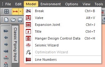
Spring Selection procedure in Caesar II
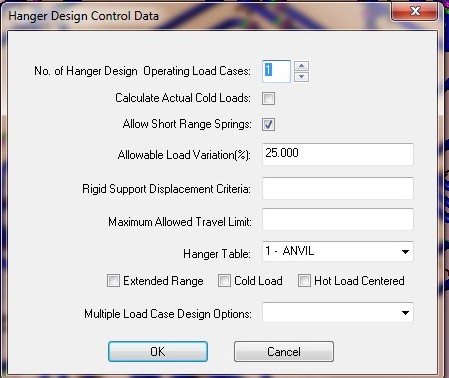
- A no. of Hangers at a given location can be selected e.g. 1 for spring on Horizontal line and 2 for spring on vertical line with trunnions.
- Calculate Actual Cold Loads:Indicates that CAESAR II makes one additional pass after the hanger design is completed and the hangers are installed, to determine the actual installed loads that should be used when the hangers are first installed and the load flanges adjusted in the field. This calculation tends to be important in the following situations:
- The stiffness of the piping system is small
- The stiffness of the hanger selected is high
- The hanger travel is large. This is usually more important in smaller diameter piping systems that are spring supported away from equipment nozzles.
- Actual cold loads should be calculated when springs in smaller diameter lines are to be adjusted in the cold position.
- Always select short range springs
- Maximum allowable load variation shall not exceed 25%
- Rigid support Displacement Criteria: This is te minimum amount of spring travel. Usually this cell if left blank.
- Maximum allowed travel limit: indicates the maximum vertical movement allowed beyond which a constant effort spring will be selected.
- Hanger Table: select the prefered vendor from the list
- Multiple Load Case Design Options: Select the maximum load and maximum travel case (Usually Maximum Design Temperature case)
- CAESAR-II Piping Input Sheet for Spring Hangers
If we double click on the Hangers in the Piping Input sheet, Spring Hanger parameters sheet will be activated as shown below
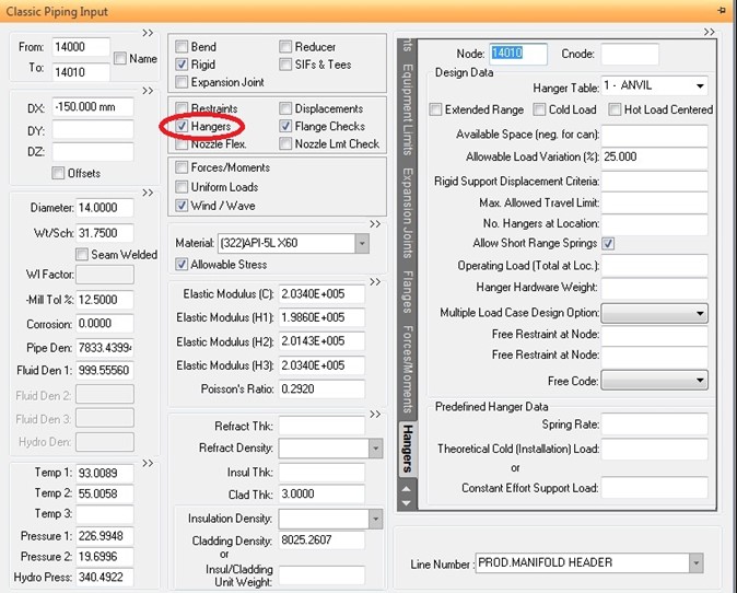
- Select the node no. where the spring has to be used
- Hanger Table will show the Vendor selected in the ‘Hanger Design Control Data’, however it can be changed
- Available space shall be left blank in case of Hanger type spring but for ‘CAN’ type spring the space available for installation of the spring shall be entered. CAESAR-II will help in selecting a suitable CAN type spring based on the space available.
- Allowable load variations will show same value as in the ‘Hanger Design Control Data’, however this can be changed.
- Select short range spring and take a preliminary run
- Edit the load cases to include the spring effect.
- Spring shall be designed at Operating Temperature
- Note down the Hot load at Operating temperature and enter in the Operating load cell
- Select Maximum load and travel case (Usually Maximum design temperature)
- Free Restraint at node: Anchor or Restraints from equipment connections which are very near to the hangers are usually freed during the hanger design restrained weight run, so that loads normally going to the equipment nozzle are carried by the hanger. The hanger can be designed to take almost the full weight of the pipe between the anchor and the hanger.
Using this field enter the node number & the direction in which free code is to be used. - Predefined Hanger Data: After finalizing the spring enter the Spring Rate and Cold Load for Variable Spring Hanger or Constant Effort for Constant Spring Hanger.