NEMA – SM 23 requires that the forces and moments acting on steam turbines due to the steam inlet, extraction, and exhaust connections should be evaluated by simple set of force/moment calculation similar to centrifugal compressors. These computations shall be done as below.
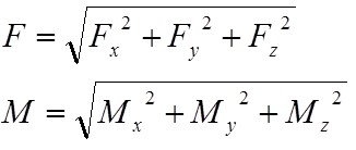
- The total resultant force and total resultant moment imposed on the turbine at any connection should not exceed the values calculated as per the following equation.
3 F + M < 500D or F < (500D – M)/3
Where,
F = Resultant force (lbs) including pressure forces where unrestrained expansion joints are used at the connection except on vertical exhausts. Full vacuum load is allowed on vertical down exhaust flanges.
D = Nominal pipe size of the connection in inches up to 8 inches in diameter.
For sizes greater than this, use a value of
D (in inches) = (16 + IPS) Inches / 3
- The combined resultants of the forces and moments of the inlet, extraction, and exhaust connections, resolved at the center line of the exhaust connection should not exceed the following two conditions.
These resultants shall not exceed:
FC = (250DC – MC)/2
Where,
FC = Combined resultant of inlet, extraction, and exhaust forces, in lbs.
MC = Combined resultant of inlet, extraction, and exhaust moments, and moments resulting from forces, in ft lbs.
DC = Diameter (in inches) of a circular opening equal to the total areas of the inlet, extraction, and exhaust openings up to a value of nine inches in diameter.
For values beyond this, use a value of Dc (in inches) equal to:
(18 + Equivalent diameter in inches) /3
The components of these resultants should not exceed:
Fx = 50 Dc Mx = 250 Dc
Fy = 125Dc My = 125 Dc
Fz = 100 Dc Mz = 125 Dc
The components are as follows:
Fx = Horizontal components of Fc parallel to the turbine shaft.
Fy = Vertical component of Fc
Fz = Horizontal component of Fc at right angles to the turbine shaft.
Mx = Component of Mc around the horizontal axis parallel to the turbine shaft
My = Component of Mc around the vertical axis
Mz = Component of Mc around the horizontal axis at right angles to the turbine shaft.
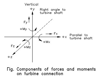
Components of forces and moments on turbine connection
- For installation of turbines with a vertical exhaust and an unrestrained expansion joint at the exhaust, an additional amount of force caused by pressure loading is allowed. (This additional force is perpendicular to the face of the exhaust flange and is deemed to act at its center), for this type of application, calculate the vertical force component on the exhaust connection excluding pressure loading. Compare this with one sixth of the pressure loading on the exhaust.
Use the larger of these two numbers for vertical force component on the exhaust connection in making calculations outlined in 1 and 2. The force caused by the pressure loading on the exhaust is allowed in addition to the values established by the foregoing up to a maximum value of vertical force in pounds on the exhaust connection (including pressure loading) of 15 ½ times the exhaust area in square inches.
- These values of allowable force and moment pertain to the turbine structure only. They do not pertain to the forces and moments in the connecting piping, flange, and flange bolting, which should not exceed the allowable stress as defined by applicable codes and explanatory notes.
all about steam turbines & gas turbines, power generation equipments calculations.