Tower Piping: Center for equipment layout
- A tower is usually a major part of a designer’s area. It is advisable to treat it as a central piece of equipment and extend the design around this center. Columns, towers and vertical vessels are to be arranged in a row with a common centerline if of similar size. If, however, diameters vary considerably, lining up with a common face will be found to be beneficial.
- During the initial stage of piping studies, piping designer should investigate in co-operation with vessel designer about the preference of lined up towers with interconnecting platforms, for convenient operation and maintenance access. The platforms are supported from towers. In such cases, slight alterations in tray spacing, internal piping arrangement, skirt height and tower length can help to put all tower manholes on same elevations. In turn lined up manholes will help platform arrangement, providing also common access to valve instrument.
- When arranging common platforms for several towers in line, allowance must be made for the differential expansion between towers. Suitably arranged hinges or slots in the platforms between towers, which introduce flexibility into the platforms shall be provided. All these feature shall be decided at the early stages of design because they affect good piping arrangement.
- Main work of tower piping is connected with the proper orientation of nozzles and provision of access to points of operation and maintenance. Generally, platforms of manholes shall be utilized for operating and maintenance access for valves and instruments. Small valves and instruments are usually arranged outside the platforms and are operated from the ladder. Additional platforms are required for operating valves, line blinds, relief valves (3” and above, orifice plates, transmitter of a level controller and handling davit.
- The operating aside is usually under pipe rack, so first ladder on tower should be on pipe rack side. To handle heavy equipment (large size relief valves, large diameter, line blinds), a davit is usually needed. The davit should be on the side of the vessel away from the rack. The area at grade should be kept clear for a dropout. for bigger diameter vessels, two davits shall be furnished. If it is located at the top of the tower, it can serve as well for lifting and lowering the top internals to grade. Clearance for the lifting tackle to all points which require handling is essential, as also sufficient access and removal space. For reactor feeding catalyst, a permanent trolley beam over the filling manholes is usually provided with adequate access at grade for lifting and removal of the catalyst.
- Fig.1 shows plan with segments of its circumference allotted to piping, nozzles, platforms and ladders, in a pattern which leads to a well-designed layout. The complete circumference of the tower is theoretically available to arrange the items. Piping should be located radially as far as possible.
- Fig.1 also shows the principal features such as manholes, platforms and pipe runs typically applicable to Tower piping arrangement. Nozzle elevations are determined by process requirements and manhole elevations by maintenance requirements. For economy and easy supports, piping should drop or rise immediately upon leaving the nozzle and run parallel and as close as possible.
- To make the orientation, follow the following steps:
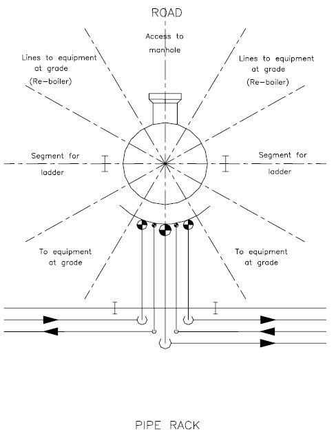
Fig 1: Piping Arrangement for Towers
Tray Orientation
Right relationship between process nozzles and tower internals is very important. This is often influenced by reboiler draw off and return nozzles and orientation by flexibility considerations. Changing from one pass to two pass, the two pass trays shall be rotated through 90 deg. to upper trays.
Nozzles & Manholes
Orientation of nozzles depends on the type of distributors and process requirements.
Before detailing, details and type of distributors must be known to the designer. Then he could produce right orientation of nozzles shall be located on tray area and must be accessible from ladder or platform.
Temperature connections are usually located in the liquid space of tray downcomers. In some cases, it could be also in vapor space. In front of thermowell nozzles, a clearance of approximately 600mm is required to remove thermowell.
Pressure connections are usually located on the vapor space just below the trays. All instrument locations are to be confirmed by process department. Care should be taken with interference such as between two reinforcing pads, one near the other, nozzle baffle and down comer and weir dams.
Manholes should preferably be placed on road side on tray area so that it is convenient for removal and lowering to grade of tower internals. Accessibility whether internal or external is very important and is often not given enough consideration. A balance must be made between the external accessibility of connections from ladders and platforms and internal accessibility from shell manholes, handholes or removable section of trays.
For example, a shell manhole opening must not be obstructed by internal piping unless the piping is removable through the manholes or can be slung clear from an internal hitching point. In either case, the break flange bolts must be accessible from the manhole.
The following considerations must be made at the initial stage of design as they bear directly on the external arrangement of tower.
1. Analyze the functions of the internals.
2. Determine the desirable location of the shell connections relative to external requirements (piping platforms).
3. Layout of the internal piping required to satisfy preferred location shell nozzle and the preferred tray orientation, and if necessary adjust these to make a workable adjustment.
Platforms, Ladders and Davit
Platforms are considered as work area for manholes and rest area when an intermediate area is added, if the height between two work platforms exceeds 9 meters.
- Generally, layout analysis should be started from the top of the tower and those having reboilers should be started from the bottom, but with the designer visualizing the layout as a whole. There will be no trouble in dropping the large lines (such as overhead vapour lines) straight down the side of the column. The lower spaces can then be laid out with piping and nozzles’ knowing what space is already occupied by these large vertical lines.Condensers are often located at grade. In such cases, a large overhead lines drop right alongside the tower to the condenser at grade. Condensers can also be elevated. An elevated condenser is more convenient from a tower piping layout standpoint because the large overhead line leaves the immediate vicinity of the tower at a high level, leaving the lower section open, say, for a ladder from grade to the first platform.
Whether the condenser is at grade or at an elevated level, the flexibility and thermal load problems connected with large diameter overhead lines must be considered.
- For valves and blinds, the best location is directly at tower nozzles. Valves in branch connections or at nozzle should be in a position where the line will be self-draining on both sides of the valve. A dead leg over closed valve collects liquid or solids. The trapped liquid can freeze, or when opening the valve, without draining the leg, can upset process conditions.All instruments should be oriented so as not to obstruct the passage way at the ladder exits or entrance. Convenient access and groupings of instruments and valve will help inspection and plant operation. Instruments should not be located adjacent to manholes.
The manhole cover can damage instruments when being swung open during maintenance.
- The tower elevation is governed by the following:
- Net positive suction head requirements if the tower bottom line is a pump suction line.
This can elevate the tower bottom tangent line. - Thermo siphon type reboiler circuit can also elevate a tower.
- Gravity flow from tower bottom or from an elevated nozzle can also elevate a tower.
- Head room requirements.
To support the tower at the chosen elevation, a steel skirt down to grade or a combination of a short steel skirt and concrete plinths will be required.
- Net positive suction head requirements if the tower bottom line is a pump suction line.
- Piping around tower shall be spaced taking into consideration the structural design of the supporting arrangement. Special care should be taken to see that supports for cold lines do not interfere with the other pipes. For supporting tower piping from tower shell, designer should select proper type. While locating clips, care shall be taken to ensure that these clips are not located on the circumferential and longitudinal weld seams indicated in the vessel date sheet.