The objective of this post is to describe the requirements for preparation and issue of Nozzle Orientation.
1. Intent of Nozzle Orientation
Nozzle Orientation drawing is prepared per equipment taking into consideration Process, Operation and maintenance requirements to:
- Orient all nozzles, manholes and lifting arrangement.
- Define equipment mounted platforms / ladders
- Orient and locate equipment supporting arrangement.
Typically Nozzle Orientation are prepared for following equipments,
- Columns and Reactors
- Horizontal / Vertical vessels
- Tanks
Nozzle Orientation is not prepared for Heat Exchangers. Specific Piping requirements shall be indicated in the form of markups on Vendor drawings.
Nozzle Orientation is issued to Vessels, Civil & Instruments department.
2. Preparation and maintenance of Nozzle Orientation
Nozzle Orientation is prepared based on study piping.
It is expected that all details of the Nozzle Orientation drawing are incorporated in Vessel / Vendor drawing. Once incorporated in Vessel / Vendor drawing, Nozzle Orientation drawing shall be deemed superseded. Any further revisions shall be made in the form of comments on Vessel / Vendor drawings.
3. Input documents required for preparation of Nozzle Orientation are as follows:
- P&ID
- Process Data Sheet
- Mechanical Data Sheet / First Pass Vendor drawings
- Vendor drawings for Column Internals
- Piping Material Specifications
- Piping Studies
- 30% Model review comments
- Instrument Level Sketches
- Piping requirements for Instruments
- Standard details for Platform and ladders.
4. Brief procedure for preparation of Nozzle Orientation shall be as follows:
4.1 Prepare the Nozzle Orientation drawing using the project specific template.
4.2 Nozzle Orientation drawings contain two basic views-
- Plan view and
- Schematic elevation
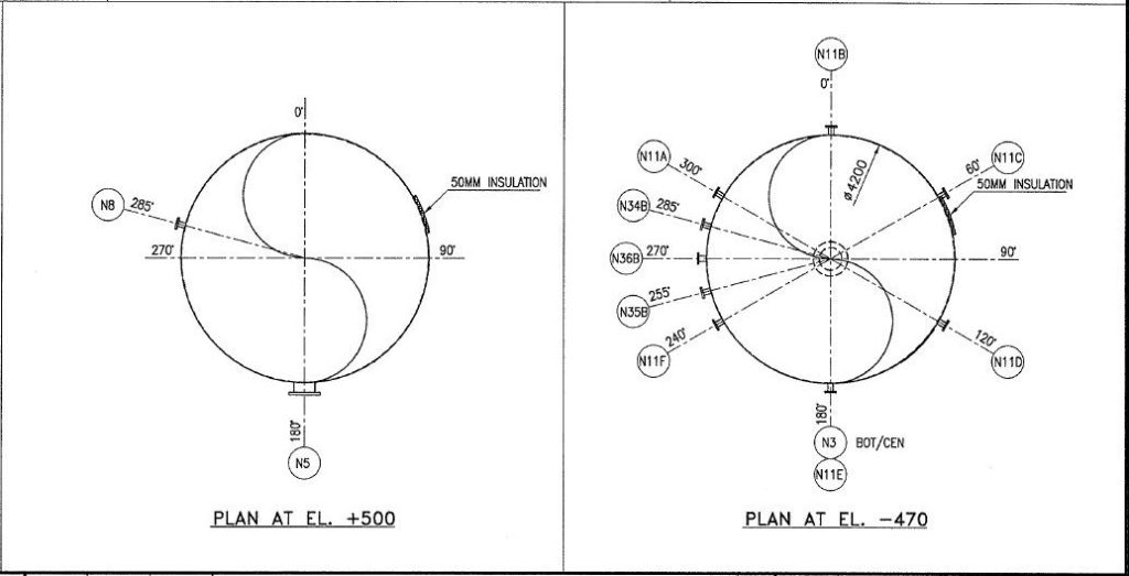
4.3 Orientation plan views shall include key information viz. nozzles, manholes, shell openings, lifting & tailing lugs, earthing bosses, name plate and davits with their tag numbers, degrees / locations.
4.4 Depending on the complexity of the nozzles various plan views shall be developed.
4.5 Schematic elevation shall indicate all the manholes, nozzles and their respective platforms / ladders, equipment supports.
4.6 For inclined horizontal Vessels only the schematic elevation view shall be furnished and no plan view shall be provided. Reference point which is the intersection of center line and fixed saddle location will govern for detailing.
4.7 Nozzles sizes / schedule and elevations shall not be included in the Nozzle Orientation.
4.8 Nozzle Orientation shall be developed with zero (0) degree aligned to the plant North and incremental degrees shall be indicated clockwise.
4.9 Permanent access platforms shall be provided for access to all manholes, valves and spectacle blinds. Permanent ladders shall be provided for access to instruments. However project specific operational requirement shall govern.
4.10 Requirements highlighted in PDS (Process Data Sheet) and Mechanical data sheet shall be taken care off before release of the nozzle orientation.
4.11 Nozzle Orientation for Columns shall take care of the column internal drawings. For trayed columns information for odd and even down comers shall be mentioned in nozzle orientation.
4.12 Davit and manhole opening shall be indicated in the Nozzle Orientation drawing. Manhole opening shall be oriented such that they are pushed closed in the escape direction.
4.13 For tall vertical Vessels and Columns, orientation study for lifting / tailing lugs and manholes shall take care of transportation and erection requirements. Lifting lugs shall be oriented 180 degree apart and tailing lug shall be located 90 degree to the lifting lug.
4.14 Reference Grade elevation shall be indicated on the Nozzle Orientation drawing. Actual plant elevations shall be indicated for:
- Bottom Tan line, U/S of support elevations for vertical Vessels and Columns.
- Centre line elevation for horizontal Vessels
- Reference point elevation for inclined horizontal Vessels
- Top of Steel for all platforms (excluding grating)
4.15 Drop out areas and maintenance davit reach shall be indicated in all the plan views.
4.16 For all vertical Vessels and Columns, platform extent shall be preferably restricted to 180 degrees.
4.17 Ladders with two side exits at the same platform elevation shall be avoided.
4.18 Inclined ladders shall not be specified. For transition at flared section of Vessel / Column or the flared support skirts straight ladders with extended support stubs to be used.
4.19 Major pipe cutouts on equipment mounted platforms shall be indicated.
4.20 If pipes are envisaged to be supported from Vessels then reference to Pipe support cleats should be covered.
4.21 Preferably ladders should be arranged with side entry
4.22 For Vertical vessels and columns ensure that anchor chairs / support lugs are located off centre and equiv spaced. For Horizontal vessels identify fixed saddle and sliding saddle on the orientation drawing.
4.23 Nozzle orientation drawings do not clear the interference issues with regards to weld seams, reinforcement pads, insulation rings and stiffeners. These issues will be coordinated and cleared for fabrication by the Vessels department.
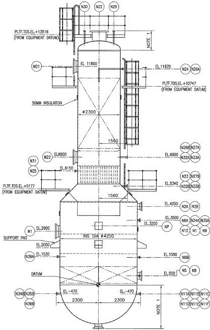
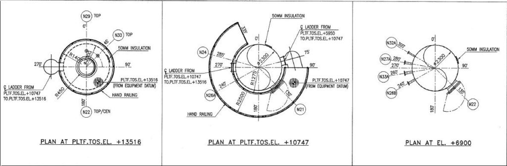
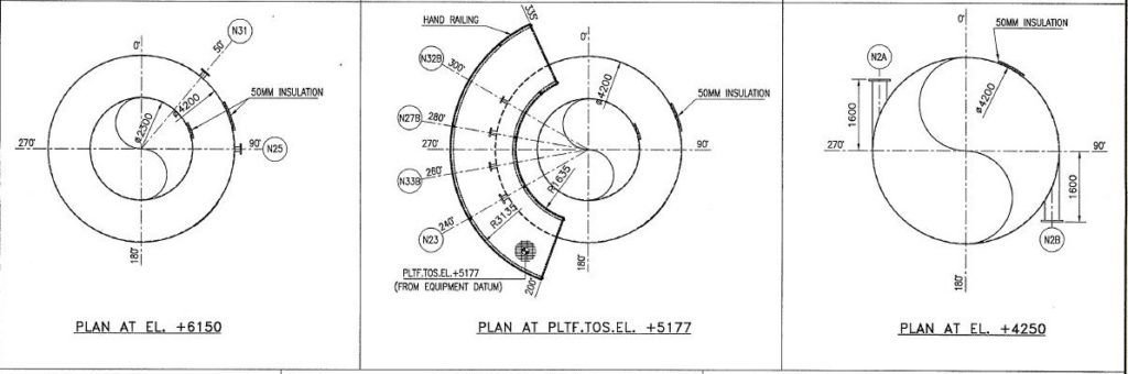
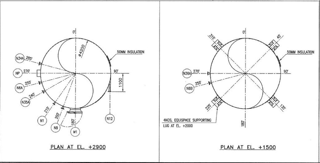
4.24 Example of Nozzle Orientation drawing:
Below example shows the nozzle orientation drawing for a vertical vessel
please as shown how to make orientation for tower please need how to make orientation for Horizontal / Vertical vessels
and Tanks
regards
Hi Ahmed,
Please refer to below article for Tower Piping which shows orientation steps-
http://www.piping-engineering.com/tower-piping-center-for-equipment-layout.html
Cheers
AJ
Very useful. Expecting more about piping design oriented
Hi Ezil,
I am not sure what exactly you are looking for, but here are few more articles on nozzle orientation and loads-
http://www.piping-engineering.com/column-piping-study-layout-nozzle-orientation-platforms-requirements.html
http://www.piping-engineering.com/nozzle-loads-part-1.html
http://www.piping-engineering.com/nozzle-loads-part-2.html
Hope these help.
AJ
Hi sir,
tell me about tank farm??
How to calculate???
Hi Raja,
You can see below posts related to tank farm-
Tank farm: Types, Design Considerations, Plot Plan Arrangement, Dyke Enclosure- Part 1
http://www.piping-engineering.com/tankfarm-types-design-considerations-plot-plan-arrangement-dyke-enclosure.html
Tank Farm: Dyke Wall Height Calculation, Piping Layout for Tank Farm- Part 2
http://www.piping-engineering.com/tankfarm-dyke-wall-height-calculation-piping-layout-for-tankfarm.html
Cheers
AJ
Tell me about tolerance for Nozzle orientation, height and protrusion?
Where are you refer ?please let me know.
I want 2d equipment or layout drawings in piping for practice in pdms.
where can I get that???
please post me the complete detailing of pipe rack piping
Hi Ranjith,
Please refer to posts below related to pipe rack study-
Introduction to piperacks:
http://www.piping-engineering.com/piperack-pipes-routing-structure-in-plant.html
Pipe rack piping study:
http://www.piping-engineering.com/pipe-rack-piping-study.html
General criteria of placing lines on the pipe rack:
http://www.piping-engineering.com/forum/pipe-rack-t6.html
Piperack or Bridge Design Flow Chart:
http://www.piping-engineering.com/piperack-bridge-design-flow-chart.html
Hope above helps.
AJ
Very good site for piping Engineering. Hats of to all the contributers….