Hierarchy in PDMS (Plant Design Management System): World, Site, Zone
In the previous post, we saw the PDMS overview. I will cover WORLD, SITE, ZONE aspects in PDMS software developed by Aveva Plant to create 3D models.
Before anyone starts modeling in the design module of PDMS, he should be well acquainted with the concept of hierarchy in PDMS i.e. WORLD, SITE & ZONE.
All PDMS data is stored in the form of a hierarchy. A PDMS Design database has:
- a top level, World (usually represented by the symbolic name /*)
- two principal administrative sublevels, Site and Zone.
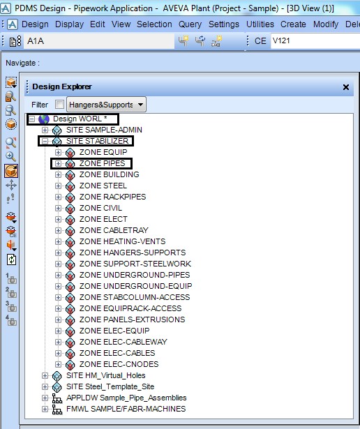
Fig.1: Hierarchy in PDMS SAMPLE project
If you login to PDMS SAMPLE project with design module, the tree shown in fig.1 appears under the Design Explorer.
At the top of the tree is WORLD which contains number of SITES. In each SITE there are number of ZONES. While modeling the designer shall model in the correct SITE & the correct ZONE as per the philosophy decided at the start of the project by the Lead Engineer & PDMS Administrator. These instructions are generally covered in the document called as 3D Modeling Execution Procedure or 3D Modeling Job Notes.
The concept of hierarchy can be explained with an example shown in fig.2
WORLD in PDMS:
The complete plant area appearing in the Plot Plan or the overall layout can be considered as “WORLD” for the Project. In the example the complete deck area highlighted in thick black border can be considered as the area available as WORLD in the PDMS. All the PDMS modeling shall be limited within this area.
SITE in PDMS:
In a project, the Plot Plan or the overall layout is divided into several sub-areas based on the sheet (A0 or A1) and the scale (eg. 1: 100 or 1:50) used for developing the equipment layout.
In the equipment layout for each sub-area there are different equipment & components of each discipline i.e. Mechanical Equipment, Piping, Electrical, Instrumentation, etc. These sub-areas are used to create SITES in PDMS.
In PDMS there are individual SITES created for different disciplines for each sub-areas. Referring to the example the deck area is divided in to four sub-areas AREA-1, AREA-2, AREA-3 & AREA-4 by the thick red lines.
For AREA-1, there are different SITES created in PDMS as PIP_AREA-1, EQUIP_AREA-1, STRU_AREA-1, ELEC_AREA-1, INSTR_AREA-1 for modeling of Piping, Equipment, Structural, Electrical & Instrumentation respectively. Similar SITES will be created for each of the sub-areas.
ZONE in PDMS:
In each of the SITES created there are different categories of components which are required to be modeled under each discipline.
For each category there is a ZONE created in PDMS.
eg. In a project there are different fluid codes or services (i.e. CD, CO, FW, OD, etc.), so the pipes can be categorized as per the fluid codes or services. Using the above categorization in the example there are different ZONES created for each fluid code or service as PAREA-1/PIPE-CD, PAREA-1/PIPE-CO, PAREA-1/PIPE-FW, PAREA-1/PIPE-OD.
The above split of WORLD, SITE & ZONE can be seen in the Fig.3.
Generally in a project the creation of SITES & ZONES is the responsibility of PDMS administrator.
The PDMS designer will not have permission to create SITE & ZONE in the project. PDMS designer has the rights only to model the equipment & component in the ZONE.
So while modeling the PDMS designer has to check the physical location of the component on the Plot plan & equipment layout then select the proper ZONE in PDMS before start of the modeling.
In the example shown in fig.2, to model a pipe with line number CD-4”-AL0NL1-PP in AREA-1 you should be on the ZONE PAREA-1/PIPE-CD to model the pipe.
The names used to identify database levels below Zone depend on the specific engineering discipline for which the data is used. For piping design data, the lower administrative levels (and their PDMS abbreviations) are:
• Pipe (PIPE)
• Branch (BRAN)
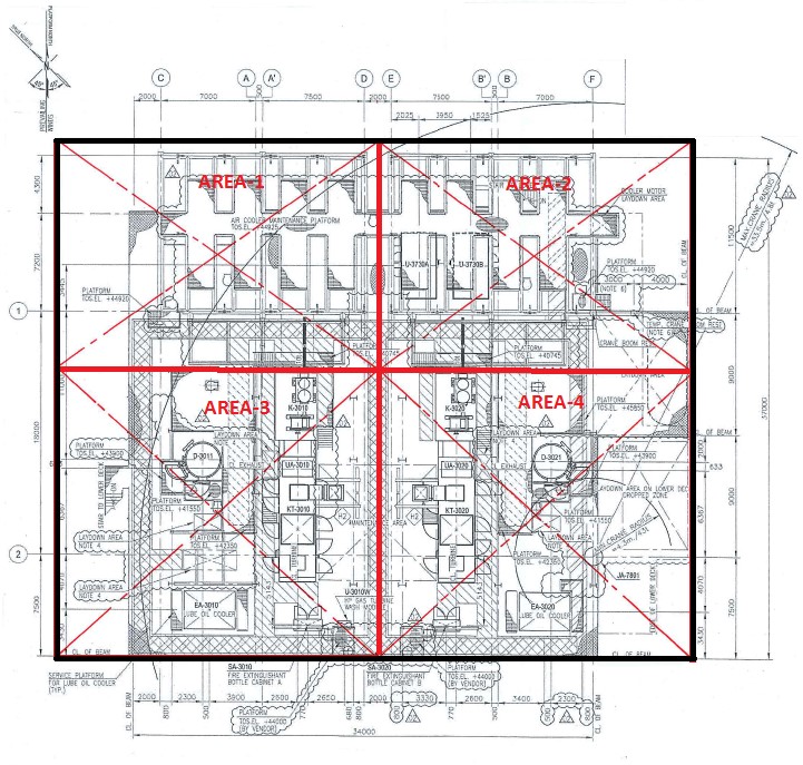
Fig .2: Example of a Deck layout
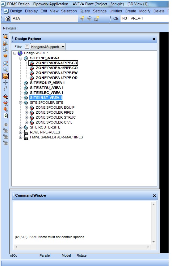
Fig .3: Hierarchy in PDMS for EXAMPLE project