1.0 INTRODUCTION TO PIPING ENGINEERING:
Since piping engineering is central to detail engineering activity and the piping engineer more or less acts as the chief coordinator, a good grasp of the working and requirement of the other engineering disciplines is essential for successfully delivering quality detailed engineering within the allotted time. Let us briefly discuss the issues concerning the piping engineer and knowledge level required in other branches of engineering to discharge his duties.
2.0 KNOWLEDGE OF PROCESS ENGINEERING:
A Piping Engineer is not expected to know Reaction kinetics or sizing of a Control or a Safety Valve. However, a basic understanding of the process is essential since the plant concept in the form of P&ID’s, piping specifications, equipment data sheets, instrument specs, etc., requires to be translated into an operating plant through detailing followed by procurement of the right equipment and other items and their proper assembly/ erection. To understand a P&ID well, an understanding of the flow of material/ fluids and their control through instrument loops is essential. For example, the P&ID may show a drain line with a slope. In reality, however, the starting end of the line, may be at a lower elevation. It therefore becomes quite difficult to run the line on the pipe rack. Under such circumstances an appropriate solution has to be found in consultation with the process department. Similarly, ball valves might have been shown for isolation of a level gauge. The ball valve handle may obstruct either the instrument or may foul with the vessel. It would, therefore, be preferable to change the above valve to a gate valve in this instance in consultation with Process Group.
Many a time gravity flow lines are not clearly shown and unless the process is fully understood, it may be difficult to route them at the correct elevation. Where gravity flow lines are shown, piping has to ensure that there is no loop in the circuit and if provision of a loop becomes unavoidable, one has to ensure that the outlet nozzle of the tank from which the fluid flows, is always at a higher elevation than the inlet nozzle of the tank in to which the fluid flows. Wherever there is separator of two miscible liquids, the bottom liquid is removed through a siphon and the siphon height should be shown on the P&ID. In gas lines, connection must be taken from the top and must be clearly indicated on the P&ID.
Concerning heat exchangers, co-current or counter-current, P&ID must match with equipment data sheet.
Simple details like vents of safety valves, flare height etc. as shown in the P&ID has to be checked by piping to ensure that they are practicable and conform to the standards.
Utility requirement at different consumer points must be clearly indicated, as the utility flow distribution chart is to be prepared by the Piping Department.
Acid proof tiling or requirement of a special floor finish should be reflected in the P&ID.
Wherever acid or corrosive chemicals are used appropriate chemical resistant tiling should be considered in all such area where the acid / chemical is likely to come in contact with.
Wherever glass lined equipment are shown in P&ID, care must be taken to ensure that the temperature differential is within the specified limits as otherwise the vessel can get damaged.
A base understanding of the process can help avoiding any such eventuality.
In all the Process & Instrument Diagrams, the process department gives the line size, fluid media and material of construction. Further filling up of P&ID, line list etc. is carried out by the piping group. A thorough study of the process can help in the proper selection of rating for components and help reduce the overall cost of the project.
Many a time, the process department would indicate on the P&ID, gravity flow lines with the maximum number of bends permitted. Piping Engineer must make every effort to reduce the number of bends without affecting the aesthetic appearance of the piping scheme.
The other important aspect to be noted in the P&ID, are the Symbols. The Symbols used must be of international Standard so that there is no confusion in understanding or reading a P&ID. A good knowledge of fluid flow and understanding of pressure drop is very useful.
3.0 KNOWLEDGE OF OTHER BRANCHES OF ENGINEERING:
The P&ID indicates each and every instrument required for indicating or controlling the process variable / parameter. Instruments may be local indicators, like temperature or pressure gauges or may be remote transmitters feeding data to panel instruments – indicators, recorders or controllers. Controllers could be P, PI or PID (i.e. Proportional, integral and derivative) types. Control instruments may be electronic or pneumatic types. The piping Engineer must have working knowledge of various instruments and their types.
Pneumatic instrumentation will have compressed instrument air connections and electronic type will have electric power / signal connection. The P&ID also indicates the interlocking scheme for process control or emergency shutdown system.
The P&ID shows each and every motor required for rotating equipment, agitator or any other electrically driven equipment. Gearbox requirements, if any, are to be indicated in the P&ID, which should be understood correctly. In some cases process control may be through electrical means and must be so indicated.
Piping Engineer should have a fairly good idea about sizing of equipment, various codes and engineering practices, stress and strain theory and such other basic principles. This is required, as many a times, he has to check vendor drawings and clear them for fabrication with the help of the Mechanical Engineer.
A basic knowledge of metallurgy is required. This will help the Piping Engineer in analyzing the reasons for selection of particular material of construction for pipes and piping items vis-avis the fluids that are required to be handled by them. Knowledge of metallurgy makes it easier to understand why code specifies certain heat treatment requirements and why quite often a higher corrosion allowance is provided.
The other branch of engineering where a lot of close co-ordination is required is Civil Engineering. Knowledge of columns, beams and other structural items / details help in fulfilling the requirements of piping in an effective manner. Requirements of insert plates, culverts and drains, pipe bridges or sleepers and other requirements are indicated by piping.
Similarly, floor finish or slopes in the right direction etc, are indicated by the Piping department.
4.0 INTERFACE WITH OTHER DEPARTMENTS:
The following are the highlights of the major activities where interdepartmental discussions are necessary before the documents are released for execution.
Piping / Civil:
- Civil Skeleton/ Civil Information Drawings of Units, Pipe Rack and Tank Farms.
- Civil Drawing review/ release for construction.
- Release of HOLDS at subsequent dates.
Piping/ Mechanical:
- Nozzle Index and Nozzle Orientation.
- Foundation Bolt details and orientation.
- Platforms Cleats on Equipment – its orientation and levels etc.
Piping/ Process:
- Review/ Markup on PID’s
- Package Units Drawings from Vendors – its review fir fixing the Battery Limit supply, General Arrangement, Civil details etc.
- Special Parts List – fixing responsibility for procurement action (i.e. by PI, PE or MQ Group).
Piping/ Procurement:
- Issue Enquiry Specification for PI Items.
- Issue Revision of MTO at subsequent dates for necessary procurement action.
- Issue Order Specification for Valves/ Special Parts. For Piping items like Flanges, Fittings, Fasteners, Gaskets etc. Procurement Department issues the Order Specifications.
- Discussions with various Vendors during bid evaluation.
Piping/ Project Management:
- Finalization of Master Plot Plan after getting clearance/ agreement with Licensor, Client, Statutory Bodies etc.
- Finalization of Procurement Philosophy/ Spare Philosophy with Client
- Monitoring of Project Schedule and updating the month wise activity and follow-up/ coordination with Client, Vendor and Licensor.
- Progress Report/ Constraint Report.
Piping/ Electrical:
- Finalization of Cable Tray Layout and requirement of Insert Plates on RCC Column/ Beam, Floor opening for Cables etc.
- Cable connection/ Push Button supports near the Terminal Box of all motors.
- Finalization of location of Switchboards, Lighting Fixtures floor wise.
Piping/ Instruments:
- Review of IC comments on the PID revision due to change in any instrument.
- Finalization of Instrumentation GES regarding connection details of Instruments and delineation of scope of procurement between PI and IC.
- Details of Instrument mountings/ dimensions.
- Review of approved Vendor Drawings for Instruments with respect to Isometrics (released for construction) as well as the piping arrangement around the Instrument.
- Finalization of IC Cable Tray requirement.
- Review of field routed instrument Cable Trays, keeping provision of accessibility, free space and interference with piping arrangement.
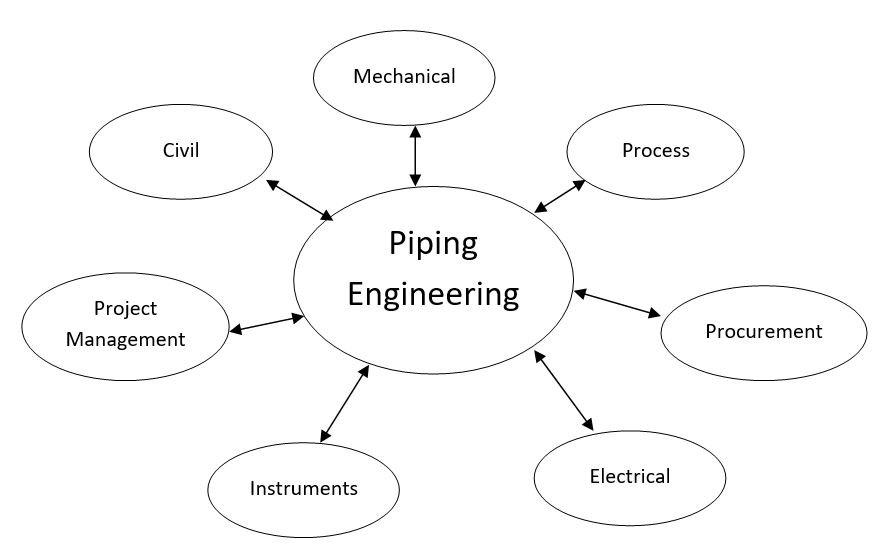
Fig 1: Various interfaces to Piping Engineering